CIRCUTOR CVM-B Series User Manual
Page 210
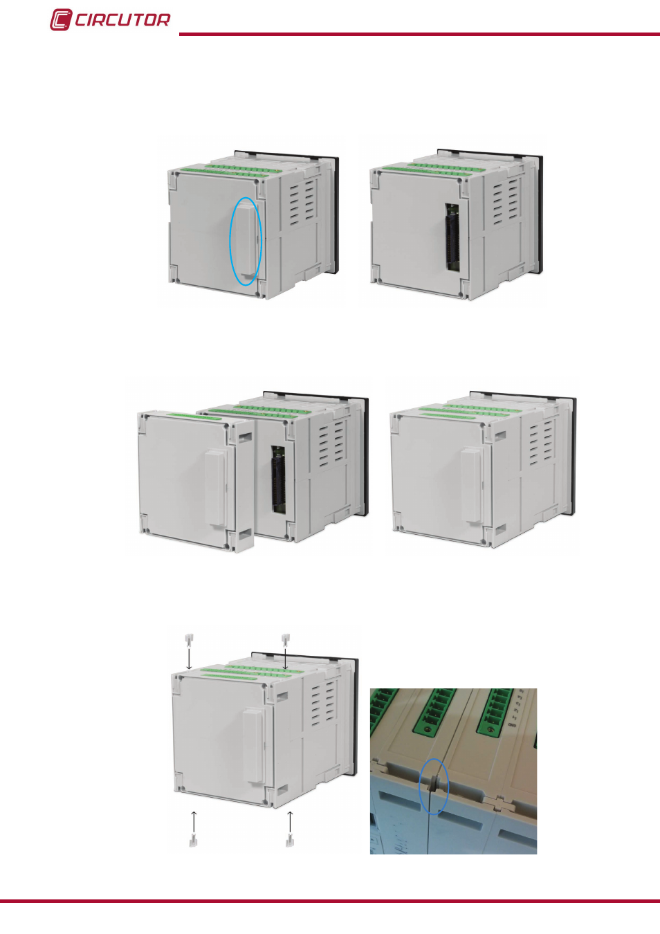
A�- Protective cove version 1
To install, firstly remove the protective cover of the expansion connector located at the rear of
the unit,
figure 142: Remove the expansion connector cap�
connect the expansion module to the unit,
,
figure 143: Connect the expansion module�
and secure it by inserting the 4 fastening pins into the corresponding slots,
.
figure 144: Insert the fastening pins into the corresponding slots�
210
CVM-B100 - CVM-B150
Instruction Manual
See also other documents in the category CIRCUTOR Measuring instruments:
- CVMk2 Series (152 pages)
- QNA500 series (111 pages)
- Wi-beee Series (32 pages)
- CVM-C5 Series (40 pages)
- CVM-C10 Series (82 pages)
- CVM-MINI Series (26 pages)
- CVM-NET Series (2 pages)
- CVM-NET4 (7 pages)
- CVM-1D Series (2 pages)
- CVM-BDM Series (32 pages)
- PowerNet Series (2 pages)
- CVM-NRG96 Series (Available until stocks) (38 pages)
- CVM96 Series (44 pages)
- CVM144 Series (58 pages)
- RS2RS (2 pages)
- TCP1RS+ (2 pages)
- EDS Series (5 pages)
- CMBUS series (24 pages)
- EDS-3G Series (6 pages)
- MDC-4 (30 pages)
- LM50-TCP+ (2 pages)
- MDC-20 (58 pages)
- ReadWatt Series (22 pages)
- CIRLAMP Series (102 pages)
- PowerStudio Series (42 pages)
- PowerStudio Series (110 pages)
- PowerStudio Series (110 pages)
- PowerStudio Series (292 pages)
- OPC Server PS/PSS (22 pages)
- SQL Data Export (28 pages)
- AR6 Series (69 pages)
- AR5L Series (52 pages)
- CIRe3 Series (50 pages)
- CIReQ (36 pages)
- QNA-P Series (36 pages)
- T3V Series (8 pages)
- CPM (Available until stocks) (20 pages)
- DHB Series (58 pages)
- DHB Series (46 pages)
- DHB Series (54 pages)
- DHB Series (50 pages)
- EMF-EMB Series (11 pages)
- SYNCHROMAX Series (2 pages)
- SYNCHROMAX Series (2 pages)