CIRCUTOR TCP1RS+ User Manual
CIRCUTOR Measuring instruments
TCP1RS+
M98253301-03-14A
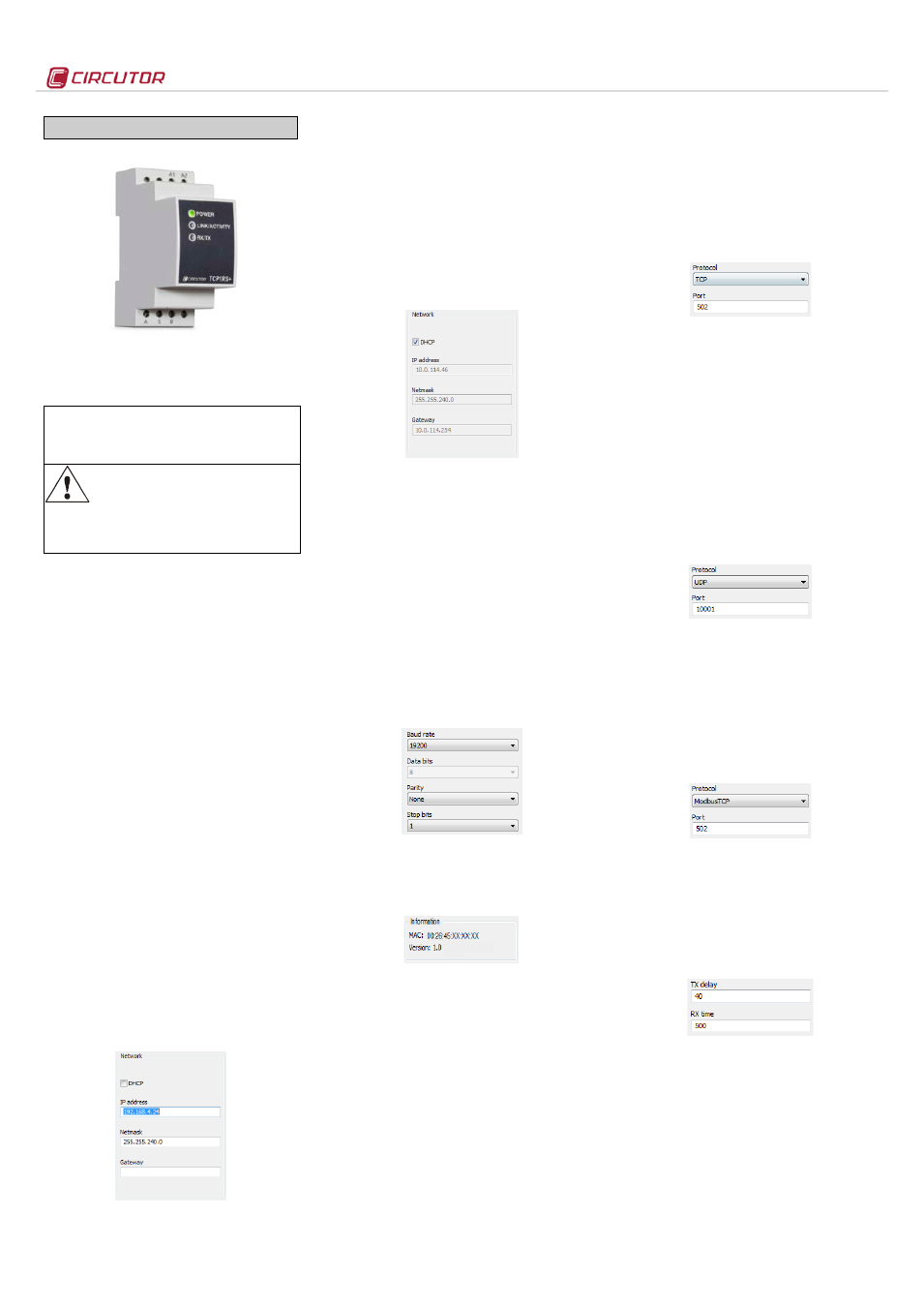
TCP1RS+
The TCP1RS+ is a communications gateway that
converts the Ethernet physical environment to RS-
485 serial communications.
This document provides the instructions for use and describes
the operation of the TCP1RS + device. If misplaced, the
manual may be downloaded from the CIRCUTOR web site:
www.circutor.com
Disconnect the device from the power
supply source before undertaking any
maintenance, modification of connections,
repairs, etc. If you suspect an operational
fault in the unit or in its protection system, remove the
unit from service. The design of the unit makes it easy
to replace in the event of a fault.
1.- DESCRIPTION
The TCP1RS+ device is a serial physical
environment to Ethernet communications converter
that uses TCP/IP communication packages. The
gateway is responsible for the transparent conversion
under TCP or UDP connections. The operation is
determined by the parameterisation carried out in the
internal configuration web menu.
2.- COMMUNICATION
The device is equipped with a self-detecting
10BaseT / 100Base TX connection for the physical
connection of the TCP1RS+ converter to an Ethernet
network. For its configuration, the device has an
internal web site from which the user can define the
network protocol used to communicate with the
management software or communications system
master.
2.1.- Ethernet addressing
As the unit is connected to the master
communication system by means of an IP
connection, the addressing parameters must be
configured. The configuration modes include the
assignment of a fixed IP or configuration of a DHCP
name.
2.1.1.- Ethernet address assignment
To configure the IP address configuration in any of
the available formats, run the IPSetup.exe
executable supplied with the unit.
2.1.2.- Fixed IP assignment
Run IPSetup and select the TCP1RS+ converter. To
assign the fixed IP address, enter the MAC address
shown on the permanent side label attached to the
device, the format of which is 00:26:45:XX:XX:XX.
In the IP Address field, enter the IP address being
configured; do the same with the Netmask and the
Gateway if necessary. After entering the device
configuration, press “Configure” to send the
configuration to the unit.
2.1.3.- DHCP IP assignment
To assign the DHCP name, activate this option by
clicking on the DHCP checkbox. Once the
configuration fields have been enabled, enter the
MAC address that can be seen on the permanent
side label attached to the device, the format of which
is 00:26:45:XX:XX:XX. In the Address, field, enter a
free temporary IP address, which is within the
working range of your computer.
2.2.- Configuration
Once the unit is connected to the Local Area
Network (LAN) and the IP address is configured or in
the DHCP mode, the remaining configuration can be
established in the IPSetup software console. When
the unit has been fully configured, the configuration
can be sent by clicking on “Configure”.
2.2.1.- Network protocol
The unit can be connected to the master
communications system by means of three types of
network protocols and to a configurable port (TCP,
UDP or Modbus/TCP).
2.2.2.- Configuration of the Serial port
The communication parameters of the serial bus are
fully configurable in terms of baud rate (1.2 bps to
115.2 kbps), data bits (7 or 8), parity (none, odd or
even) and stop bits (1 or 2). The data will be
configured by default to 8 by selecting the
Modbus/TCP communications protocol.
2.2.3.- Device information
When the unit is connected with IPSetup, the top
part of the screen shows the firmware version and
the machine address of the device (the same
address as that shown on the permanent side label).
2.2.4.- Save changes
Once any change has been made to the
aforementioned sections, the information must be
saved using the “Configure” option. If you wish to
return to the default configuration, select “Load
default”.
2.3.- Configuration of network protocols
2.3.1.- TCP Protocol
In totocol stack, TCP is the intermediate
layer between t(IP) and the
n general, applications need reliable
communications. The IP layer offers an unreliable
datagram service (no confirmation), so the TCP adds
the functions required to offer a secure, error-free and
zero loss service for the communications between
two systems.
-
Protocol: TCP Mode
-
Port: Destination TCP Port number
2.3.2.- UDP Protocol
User Datagram Protocol (UDP) is a minimum
message-oriented protocol that has
been documented in t tIn tUDP provides a simple
interface between tand the
UDP does not offer guarantees for
the delivery of its messages and the UDP origin does
not withhold the states of UDP messages sent to the
network. UDP only adds tunctionality
to tand tof the
header and useful load. Any type of guarantees for
the transmission of information must be implemented
in higher layers.
-
Protocol: UDP Mode
-
Port: Destination UDP Port number
2.3.3.- Modbus/TCP Protocol
Modbus/TCP is a variation or extension of the
Modbus® protocol, which enables it to be used on the
TCP/IP transport layer. Therefore, Modbus/TCP can
be used throughout the Local Area Network or the
Internet. This was one of the objectives that
motivated its development (the specification of the
protocol was submitted to the IETF, Internet
Engineering Task Force).
-
Protocol: Modbus/TCP Mode
-
Port: Fixed port number 502
2.3.4.- Tx Delay Rx Time
The TCP1RS+ converter uses two communication
parameters to control the Modbus frames on the
RS485 bus.
-
Tx Delay: additional delay of the RS serial bus
-
Rx Time: maximum bus waiting time
Document Outline
- As the unit is connected to the master communication system by means of an IP connection, the addressing parameters must be configured. The configuration modes include the assignment of a fixed IP or configuration of a DHCP name.
- To configure the IP address configuration in any of the available formats, run the IPSetup.exe executable supplied with the unit.
- Run IPSetup and select the TCP1RS+ converter. To assign the fixed IP address, enter the MAC address shown on the permanent side label attached to the device, the format of which is 00:26:45:XX:XX:XX.
- In the IP Address field, enter the IP address being configured; do the same with the Netmask and the Gateway if necessary. After entering the device configuration, press “Configure” to send the configuration to the unit.
- To assign the DHCP name, activate this option by clicking on the DHCP checkbox. Once the configuration fields have been enabled, enter the MAC address that can be seen on the permanent side label attached to the device, the format of which is 00:26:45:XX:XX:XX. In the Address, field, enter a free temporary IP address, which is within the working range of your computer.
- Once the unit is connected to the Local Area Network (LAN) and the IP address is configured or in the DHCP mode, the remaining configuration can be established in the IPSetup software console. When the unit has been fully configured, the configuration can be sent by clicking on “Configure”.
- The unit can be connected to the master communications system by means of three types of network protocols and to a configurable port (TCP, UDP or Modbus/TCP).
- The communication parameters of the serial bus are fully configurable in terms of baud rate (1.2 bps to 115.2 kbps), data bits (7 or 8), parity (none, odd or even) and stop bits (1 or 2). The data will be configured by default to 8 by selecting the Modbus/TCP communications protocol.
- When the unit is connected with IPSetup, the top part of the screen shows the firmware version and the machine address of the device (the same address as that shown on the permanent side label).
- Once any change has been made to the aforementioned sections, the information must be saved using the “Configure” option. If you wish to return to the default configuration, select “Load default”.
- In the TCP/IP protocol stack, TCP is the intermediate layer between the Internet protocol (IP) and the application. In general, applications need reliable communications. The IP layer offers an unreliable datagram service (no confirmation), so the TCP adds the functions required to offer a secure, error-free and zero loss service for the communications between two systems.
- User Datagram Protocol (UDP) is a minimum transport level message-oriented protocol that has been documented in the RFC 768 of the IETF.
- In the Internet protocol family, UDP provides a simple interface between the network layer and the application layer. UDP does not offer guarantees for the delivery of its messages and the UDP origin does not withhold the states of UDP messages sent to the network. UDP only adds the multiplexing functionality to the application and the verification sum of the header and useful load. Any type of guarantees for the transmission of information must be implemented in higher layers.
- Modbus/TCP is a variation or extension of the Modbus® protocol, which enables it to be used on the TCP/IP transport layer. Therefore, Modbus/TCP can be used throughout the Local Area Network or the Internet. This was one of the objectives that motivated its development (the specification of the protocol was submitted to the IETF, Internet Engineering Task Force).
- The TCP1RS+ converter uses two communication parameters to control the Modbus frames on the RS485 bus.