Modbus communications – CIRCUTOR CVM-B Series User Manual
Page 254
7�4�4�- MODBUS COMMUNICATIONS
The address of the Modbus memory map depends on the position of the expansion module in
the unit.
Slot 1 will be the position of the expansion module installed just behind the standard unit, and
Slot 2 the next position...
As the maximum number of expansion modules that can be connected to the unit is 4, there
will only be 4 slots.
7�4�4�1�- Programming analogue outputs
The following functions are implemented for these variables:
function 0x04: reading registers.
function 0x10: Writing multiple registers.
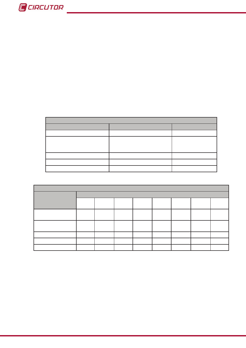
Table 111: Modbus memory map: Analogue outputs, expansion modules (Table 1)�
Configuration of analogue outputs
Configuration variable
Valid data window
Default value
Variable code
Table 21
0
Scale
0: 0 to 20 mA
1: 4 to 20 mA
2: 0 to 10 V
0
Zero
0
Full-scale
-
Module no.
0
0
Table 112: Modbus memory map: Analogue outputs, expansion modules (Table 2)�
Configuration of analogue outputs: Slot 1
Configuration
variable
Address
Output
1
Output
2
Output
3
Output
4
Output
5
Output
6
Output
7
Output
8
Zero
D340 -
D341
D34A -
D34B
D354 -
D355
D35E -
D35F
D368 -
D369
D372 -
D373
D37C -
D37D
D386 -
D387
Full-scale
D342 -
D343
D34C -
D34D
D356 -
D357
D360 -
D361
D36A -
D36B
D374 -
D375
D37E -
D37F
D388 -
D389
Scale
D344
D34E
D358
D362
D36C
D376
D380
D38A
Variable code
D345
D34F
D359
D363
D36D
D377
D381
D38B
Nº de modulo
D346
D350
D35A
D364
D36E
D378
D382
D38C
Note: The 7 registers must be written and read at once (as a group), otherwise it will respond
with an error.
254
CVM-B100 - CVM-B150
Instruction Manual