EXFO FTB-8500 Series for FTB-200 User Manual
Page 98
Creating and Starting a Test Case
84
FTB-8500 Series and FTB-8120NGE/8130NGE
Ethernet RFC 2544 Test Case
Note: At this point you should have a link up indicated by the Link LED on the Port
node. A green LED indicates a link up while a grey LED indicates a link
down. For electrical port, if the link is down, make sure that the Ethernet
port crossover setting is correct.
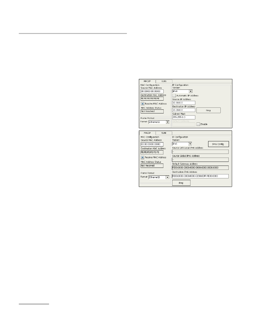
3. Press the Network node.
3a. If required, set the
network source MAC
addresse. Select the
Resolve MAC Address
check box or set the
destination MAC
address. Refer to MAC on
page 222 for more
information.
3b. Select the Frame
Format. Choices are
Ethernet II and 802.3
SNAP. Refer to Frame
Format Configuration on
page 453 for more
information.
3c. Select the IP Version (IPv4 or IPv6). IP Version is only available
when the IPv6 software option (SK-IPV6) is enabled.
3d. For IPv4, select the Automatic IP Address check box to
dynamically obtain an IP address from a DHCP (Dynamic Host
Configuration Protocol) server.
3e. Set the source and destination IP addresses (based on the
network setting) and if required set the Subnet Mask, and
Default Gateway parameters. Press the Ping button to determine
if the network device is reachable. Refer to IP/UDP/TCP on
page 227 for more information.