EXFO FTB-8500 Series for FTB-200 User Manual
Page 83
Creating and Starting a Test Case
Ethernet and Fibre Channel Application
69
EtherSAM (Y.1564) Test Case
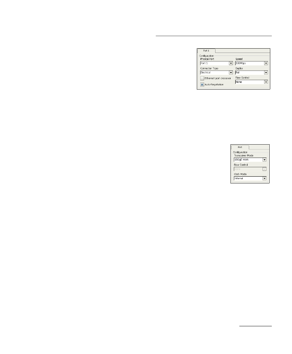
2. Press the Port node.
2a. Select the Physical Port (Port 1 or
Port 2) that will be used for the
test. The default setting is Port 1.
Available with FTB-8510B only.
2b. Select the port Connector Type
(Optical or Electrical). Connector Type is not available with
Ethernet 10G interface. The default setting is Electrical.
2c. For Electrical, if required, select the Ethernet port crossover
check box to inverse the pin-to-pair assignment of the UTP cable
used.
2d. For Ethernet 10G interface:
Select the Transceiver Mode Choices are Local
Area Network (LAN) for regular Ethernet
interface (10.313Gb/s) and Wide Area Network
for Ethernet stream encapsulated inside a
SONET/SDH frame structure (9.95328Gb/s).
Choices availability depend on the unit model and options refer to
Software Options on page 355 for more information. The default
setting is 10GigE LAN when both transceivers are supported.
For FTB-8120NGE, FTB-8130NGE, FTB-8525, and FTB-8535 with
WAN transceiver mode, select the source Clock Mode . Refer to
Clock Synchronization on page 360 for more information.
2e. For 10/100/1000 interfaces, setSet the Auto-Negotiation, Speed,
Duplex, and Flow Control parameters. Refer to Port Setup on
page 125 for more information.
Note: At this point you should have a link up indicated by the Link LED on the Port
node. A green LED indicates a link up while a grey LED indicates a link
down. For electrical port, if the link is down, make sure that the Ethernet
port crossover setting is correct.