EXFO FTB-8500 Series for FTB-200 User Manual
Page 116
Creating and Starting a Test Case
102
FTB-8500 Series and FTB-8120NGE/8130NGE
Ethernet TCP Throughput Test Case
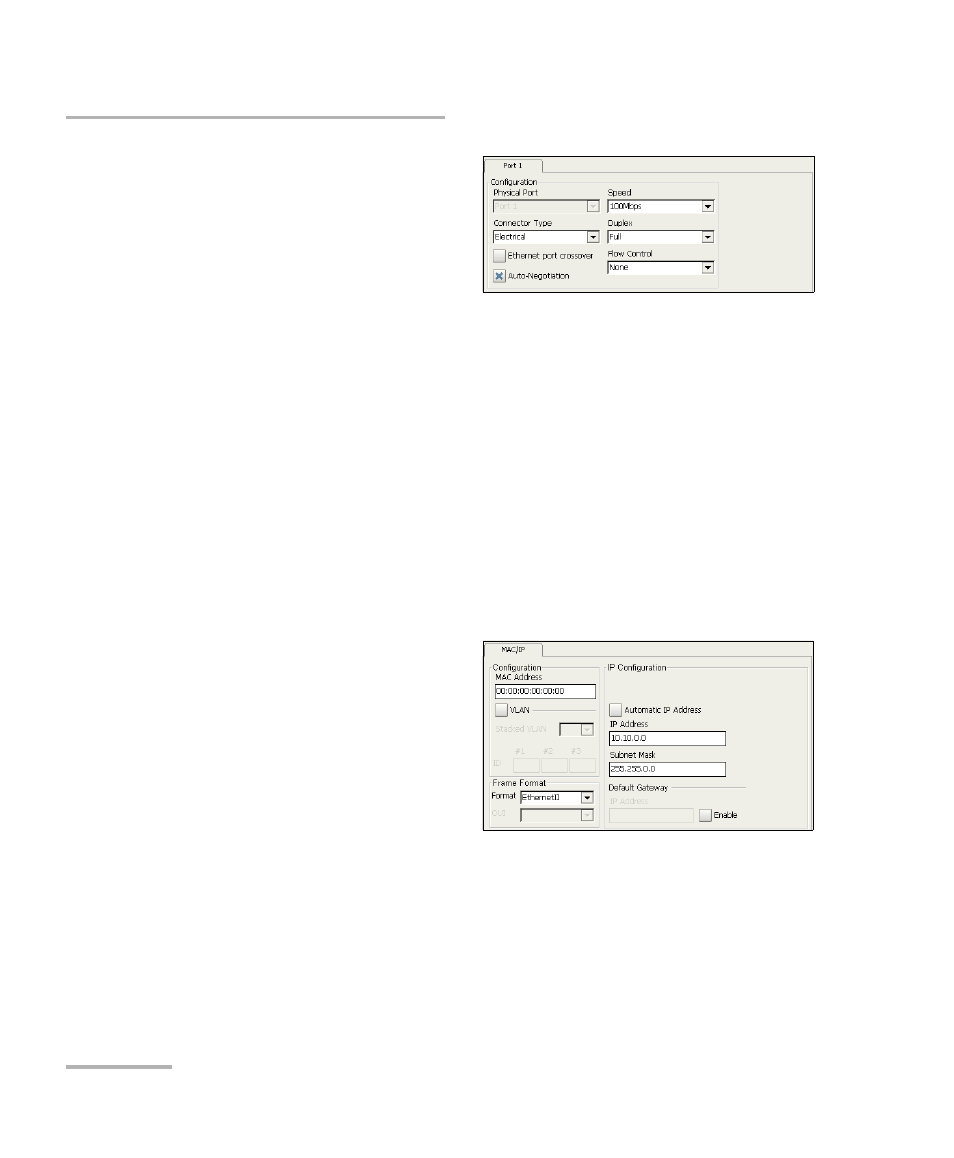
2. Press the Port node.
Port 1 (FTB-8510B only) is
automatically selected.
2a. Select the port
Connector Type
(Optical or Electrical). Connector Type is not available with
Ethernet 10G interface. The default setting is Electrical.
2b. For Electrical, if required, select the Ethernet port crossover
check box to inverse the pin-to-pair assignment of the UTP cable
used.
Note: At this point you should have a link up indicated by the Link LED on the Port
node. A green LED indicates a link up while a grey LED indicates a link
down. For electrical port, if the link is down, make sure that the Ethernet
port crossover setting is correct.
2c. Set the Auto-Negotiation, Speed, Duplex, and Flow Control
parameters. Refer to Port Setup on page 125 for more information.
3. Press the Network node.
3a. If required, set the
network MAC address
and VLAN parameters
when required. Refer to
Network Setup on
page 129 for more
information.
3b. Select the Frame Format. Choices are Ethernet II and
802.3 SNAP. Refer to Network Setup on page 129 for more
information.
3c. Set the IP Address (IPv4), Automatic IP address, Subnet Mask,
and Default Gateway parameters to complete the test setup.
Refer to IP Configuration on page 130 for more information.