Failure output pattern settings, P. 85) – Toa SX-2000 Series User Manual
Page 85
85
PATTERN SETTINGS
Failure Output Pattern Settings
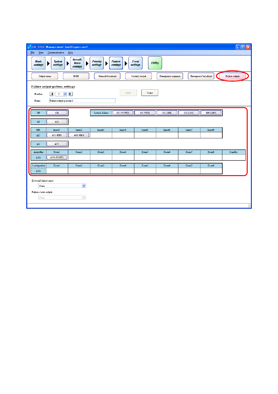
11.7. Failure Output Pattern Settings
Clicking the [Failure output] button on the pattern settings screen allows Failure output patterns to be set.
(1)
(2)
(3)
(4)
(5)
(6)
Settings made here are operatively associated with the
p. 69 "Surveillance Settings."
Select the units or the surveillance target points.
• Selecting the units (Designate the units as factors to activate failure output pattern.)
At least one or more surveillance points must be set to the unit to be selected here to enable Surveillance
function.
This failure output pattern is activated when irregularity is detected at the surveillance points of the selected
unit. Determine the method to activate the set failure output patterns using the
Characters on each setting button on the screen represent the unit names as shown below.
SM:
SX-2000SM
AI1:
SX-2000AI or SX-2100AI with device No. set to "1."
AI1-RM1:
RM-200SF and RM-210, RM-200S and RM-210, or RM-200SA and
RM-210 connected to AI1's Input 1.
AI1-RM2:
RM-200SF and RM-210, RM-200S and RM-210, or RM-200SA and
RM-210 connected to AI1's Input 2.
AO1:
SX-2000AO or SX-2100AO with Unit No. set to "1," and its connected
SX-2000CI and SX-2000CO.
AO1-ZONE 1 in Amplifier item:
External amplifier connected to the Amplifier Input terminal of AO1 used
for Zone 1.
AO1-ZONE 1 in Loudspeaker item: Speakers connected to the Speaker Connection terminals of AO1 used
for Zone 1.
• Selecting the surveillance target points (Designate the surveillance target points as factors to
activate failure output pattern.)
Each setting button in the "System failure" becomes active when the following surveillance points are marked
in any one of the units within the system in the "Surveillance Settings (
This failure output pattern is activated when irregularity is detected at the selected surveillance points set to