8 masking, 88 masking, Chapter 7 pitch mode – KEYENCE LS-5000 User Manual
Page 90
Chapter 7 Pitch Mode
84
7
8
8
8
8
8 Masking
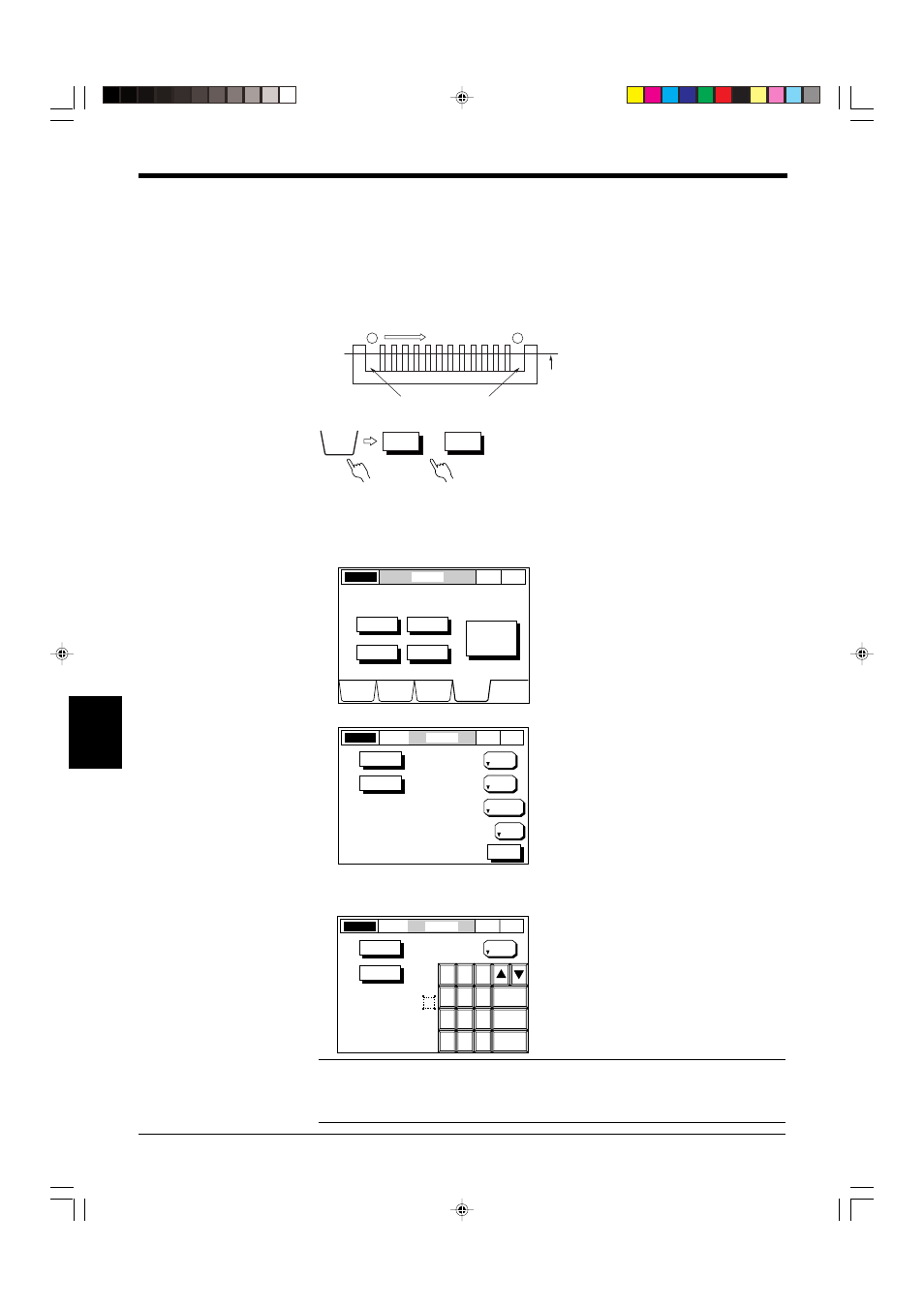
Up to three pitches can be excluded from measurement, based on the application,
as shown below.
If pitch (1) and pitch (13) are included in the measurement of connector lead
pitches as shown on the right, the maximum value becomes larger than the actual
value. The masking function is useful to cancel these unnecessary part in such a
case.
■ Setting Procedure
1. Select the OPTIONS screen. Press the [OPTIONS] button.
2. Set the masking function.
Press the button corresponding to the output for which the masking function is
to be set.
3. Press the [MASKING] button.
Enter the pitch number to be canceled using the numeric keys, and press
[ENTER]. Press [ESCAPE] to complete the entry. Press [CANCEL] to cancel
the entry. The value returns to the previous value.
Note 1: Pitch number is counted from Pitch 1 in the scanning direction (from the top of the scanning
head to the bottom).
Note 2: When the total number of pitches changes (i.e. due to lead breakage), the control I/O board’s
HI3 output is turned ON which indicates an "Error with No. of Pitches”. (Except for the self-timing mode)
1
13
Pitches to be canceled
Scanning direction
Optical
axis
HEAD1
• • •
HEAD4
OPTIONS
LASER ON
OPTIONS
P. 1
PITCH
DISPLAY
DATA
LIMIT
SETUP
PROGRAM
OPTIONS
HEAD1
HEAD2
HEAD3
HEAD4
MODE
CHANGE
Pitch
-> Normal
OPTIONS
HEAD1
LASER ON
P. 1
PITCH
MASK1:
PITCH No.
NO. OF
PITCHES
MASKING
10
0
MASK2:
PITCH No.
0
MASK3:
PITCH No.
0
AVERAGE
8
DIGIT
SUPPRESS
NONE
MEASUR-
ING MODE
NORMAL
SELF-TIMING
INTERVAL (ms)
100
ESC
OPTIONS
HEAD1
LASER ON
P. 1
PITCH
8
7
5
6
4
2
3
1
0
9
ENTER
CANCEL
ESCAPE
NO. OF
PITCHES
MASKING
10
AVERAGE
8
MASK1:
PITCH No.
0
MASK2:
PITCH No.
0
MASK3:
PITCH No.
0
In this example, set the No. of Pitches to 13.
In this example, set MASK1 to 1 and MASK2 to 13.