1 system configuration and connections, 1 system configuration – KEYENCE LS-5000 User Manual
Page 14
Chapter 2 Before Using the LS-5000 Series
8
2
2.1
System Configuration and Connections
The LS-5000 series includes the display unit, controller and scanning head.
This section describes the system configuration and connections of the LS-5000
series.
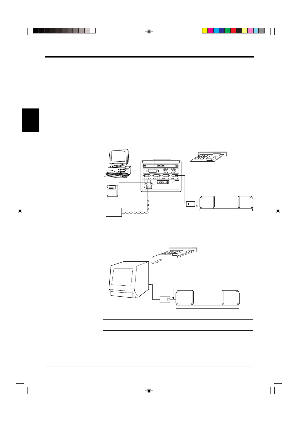
2.1.1 System Configuration
The LS-5000 series includes the display unit, controller and scanning head. The
controller can be used separately.
The LS-5000 series also offers I/Oboard, as well as a control unit which
incorporates the display unit and controller in a single body.
•
Separate display type
•
Built-in display type
Note: The scanning head and ROM board are calibrated as a pair. Be sure to
combine the units that have the same serial number.
LS-5501
I/O board (LS-B11)
ROM board
LS-5041/5121
Connection cable (option)
LS-C3: 3m
LS-C10: 10 m
LS-C50: 50 m
24 VDC
LS-5001
LS-5041/5121
Connection cable (option)
LS-C3: 3m
LS-C10: 10 m
LS-C50: 50 m
ROM
board
Expansion slots
Power
supply
I/O board (LS-B11)
Personal computer
LS-VIEWER
operating software
for Windows 95