2 limit setup, 22 limit setup, Chapter 7 pitch mode – KEYENCE LS-5000 User Manual
Page 81
Chapter 7 Pitch Mode
75
7
2
2
2
2
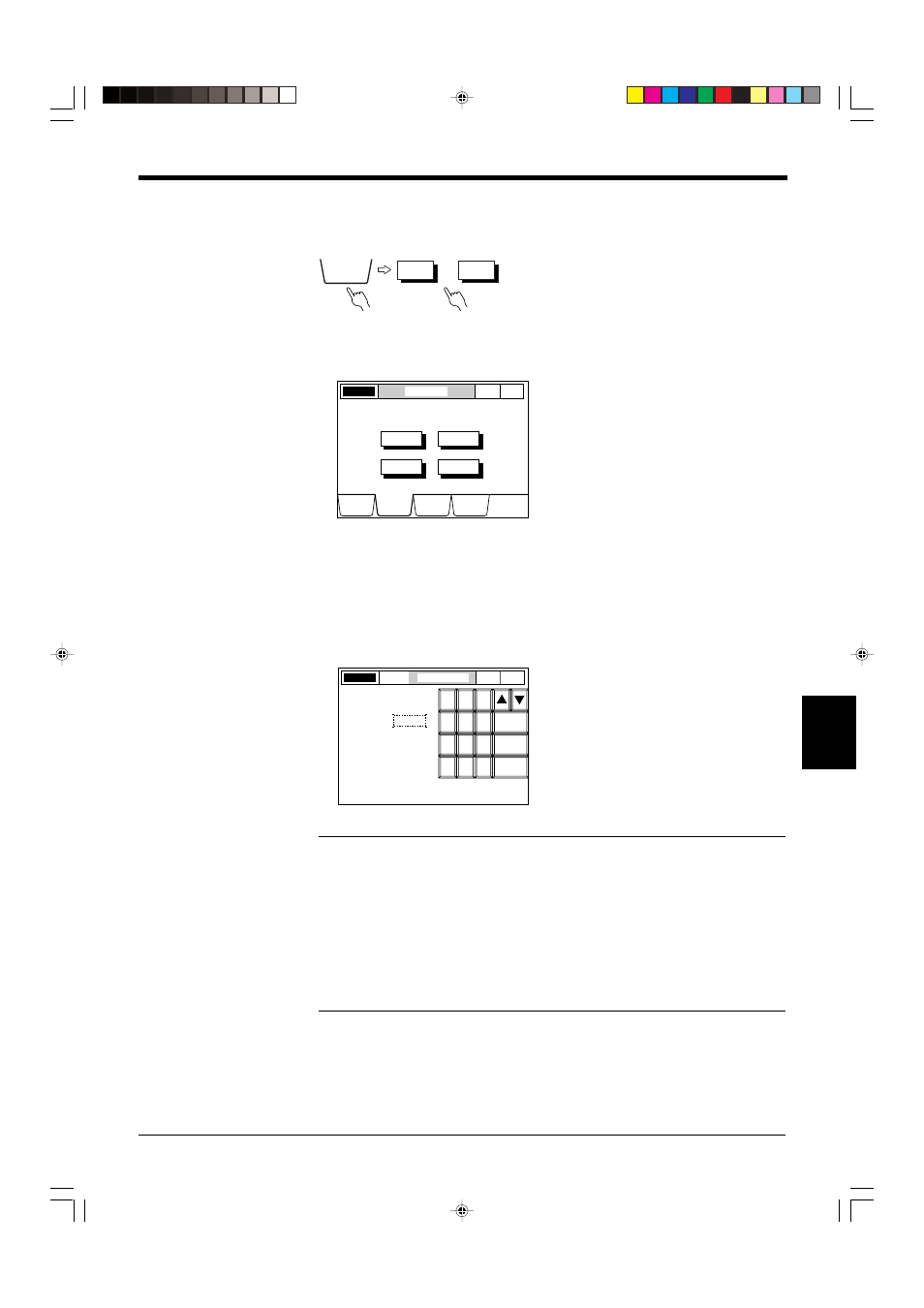
2 Limit Setup
The reference value, upper limit, and lower limit can be set separately for each of
the four scanning heads.
■ Setting Procedure
1. Select the LIMIT SETUP screen.
Press the [LIMIT SETUP] button.
2. Set tolerance limits.
Press the button corresponding to the output for which tolerance limits are to be
set.
Set tolerance limits using the numeric keys, and press [ENTER].
Press [ESCAPE] to complete the entry.
Press [CANCEL] to cancel the entry. The value returns to the previous value.
Note: When the measured value exceeds the tolerance range, the value is dis-
played in reverse. The differentiation result relative to the tolerance limits is output
from the display unit and the control I/O board (optional).
When the measured value exceeds the upper limit or falls below the lower limit, the
HI1 output is turned on.
In PITCH mode, the Upper-Lower Limit indicates the difference from the Reference
value. If a measured value of more than 1.1000 mm is to be checked and the
Reference value is set to 1.000 mm, the Upper Limit should be +0.1000. If 0.9000
mm is to be checked, the Lower Limit should be -0.1000 mm.
HEAD1
• • •
HEAD4
LIMIT
SETUP
LASER ON
LIMIT SETUP
P. 1
PITCH
DISPLAY
DATA
LIMIT
SETUP
PROGRAM
OPTIONS
HEAD1
HEAD2
HEAD3
HEAD4
Select Head to set the limits.
LIMIT SETUP
HEAD1
LASER ON
P. 1
PITCH
8
7
5
6
4
2
3
1
0
9
ENTER
CANCEL
ESCAPE
+0.0100
1.0000
UPPER LIMIT:
REFERENCE:
LOWER LIMIT:
-0.0100