1 dia mode, 3 seg (m,n) mode – KEYENCE LS-5000 User Manual
Page 29
Chapter 5 Outline of Measurements
23
5
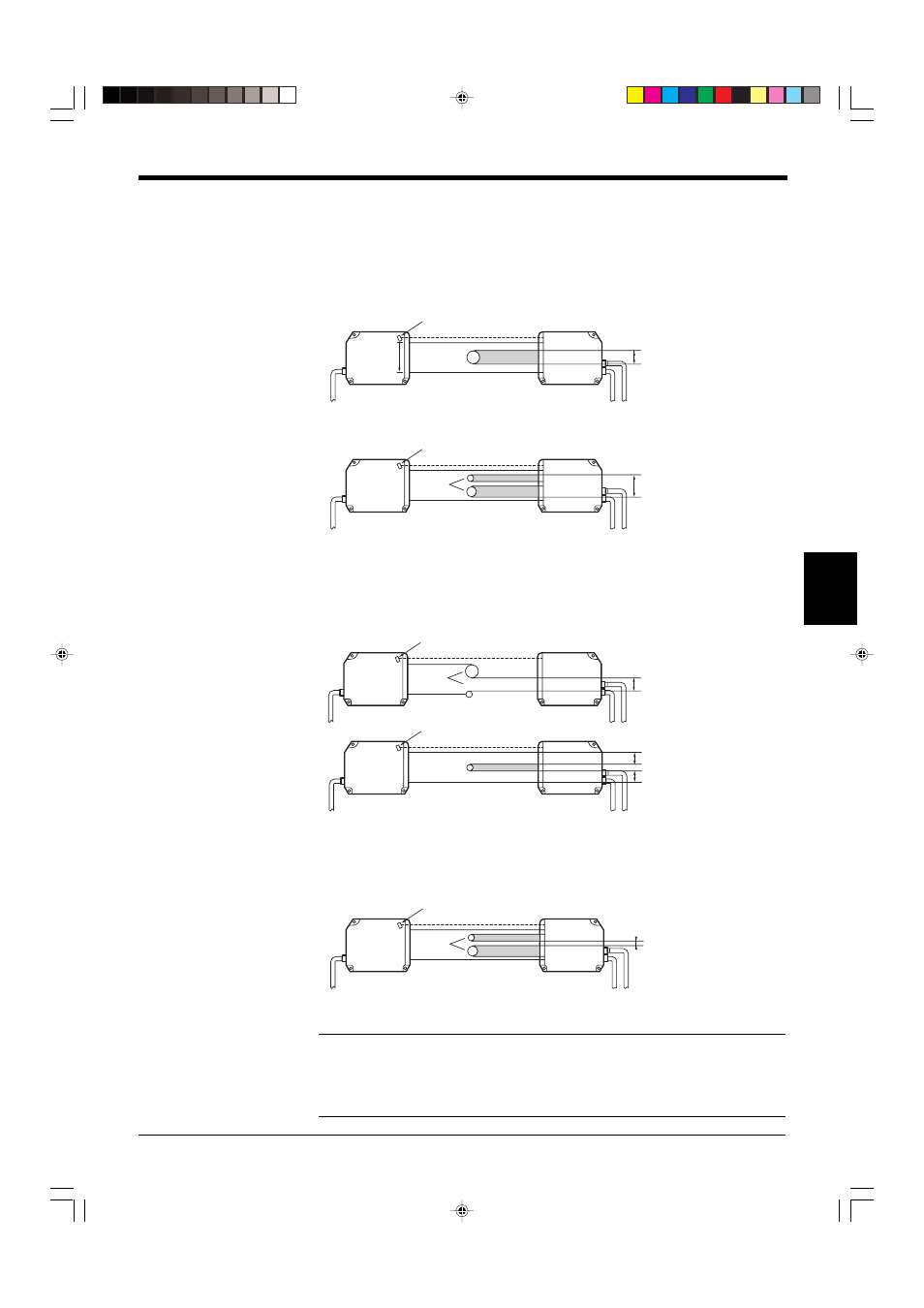
5.2.1 DIA Mode
Example: Outer diameter measurement using a rod or transparent object
The width between the lower edge of the first light segment and the top edge of the
last light segment is measured.
•
When one target is measured
•
When several targets are measured
5.2.2 T.EDGE (TOP EDGE) Mode / B.EDGE (BOTTOM EDGE) Mode
Example: Measurement of a gap between rollers
T.EDGE: Measures the width of the first light segment.
B.EDGE: Measures the width of the last light segment.
5.2.3 SEG (m,n) Mode
Example: Inner diameter measurement using a bearing
When two edges are specified, the width between these edges is measured.
*
(m,n) indicates any number between 0 and 254. “m” should be smaller than “n”.
Note: DIA mode
Since DIA mode is basically intended for outer diameter measurement of a rod,
transparent tube or other round surface, the measurement error due to the round
surface is calibrated.
To perform outer diameter measurement of a round target, select DIA mode.
Photodiode for synchronization
Laser
scanning
direction
Target
Measured
width
Transmitter
Receiver
Photodiode for synchronization
Target
Measured
width
Transmitter
Receiver
Photodiode for synchronization
Target
The T.EDGE mode
measures this width.
The B.EDGE mode
measures this width.
Transmitter
Receiver
Photodiode for synchronization
Target
Both the T.EDGE and B.EDGE
modes measure this width.
Transmitter
Receiver
Photodiode for synchronization
Target
This width is measured
when SEG(3,4) is set.
Transmitter
Receiver
0
1
2
3
4
5
6