7 area setup, 77 area setup, Chapter 6 normal mode – KEYENCE LS-5000 User Manual
Page 45
Chapter 6 Normal Mode
39
6
7
7
7
7
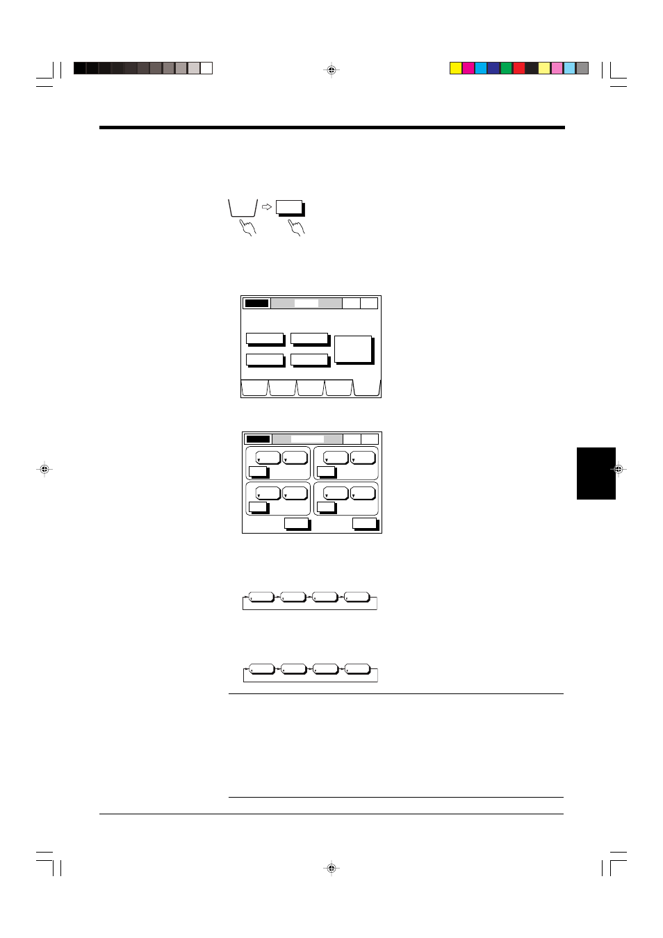
7 Area Setup
The scanning head (Head 1 to Head 4) and measuring mode (DIA, T.EDGE,
B.EDGE, SEG(m,n))can be selected for a measuring area. Up to 4 areas can be
set at the same time. (
➮ see p. 22 for Area.)
■ Setting Procedure
1. Select the OPTIONS screen.
Press the [OPTIONS] button.
2. Select the AREA SETUP screen.
Press the [AREA] button.
3. Set the scanning head number.
When you press the [HEAD No.] button, the scanning head number is switched
in the following order.
4. Set the segment.
When you press the [SEGMENT] button, the segment is switched in the follow-
ing order.
Note 1: The edge number setting is effective only when “SEG” is selected as the
SEGMENT.
Note 2: When either of DIA, T.EDGE, or B.EDGE is selected for a scanning head,
SEG cannot be selected for the same head. Also, when SEG is selected, DIA,
T.EDGE, and B.EDGE cannot be selected for the same head.
Note 3: When only one scanning head is connected, the head number remains
“HEAD 1” even if the head number button is pressed.
LASER ON
OPTIONS
NOR
MAL
P. 1
DISPLAY
DATA
LIMIT
SETUP
PROGRAM
CALIB
OPTIONS
AREA
OUTPUT
INSPECT
UTILITY
Select Option to setup.
MODE
CHANGE
Normal
-> Pitch
LASER ON
AREA SETUP
NOR
MAL
P. 1
DIA
HEAD1
( 2, 3)
ESC
HELP
SET
HEAD No.
EDGE No.
A1
SEGMENT
SEGMENT
SEGMENT
SEGMENT
DIA
HEAD2
( 2, 3)
SET
HEAD No.
EDGE No.
A2
DIA
HEAD3
( 2, 3)
SET
HEAD No.
EDGE No.
A3
DIA
HEAD4
( 2, 3)
SET
HEAD No.
EDGE No.
A4
HEAD1
HEAD2
HEAD3
HEAD4
DIA
T. EDGE
B. EDGE
SEG
OPTIONS
AREA