2 mounting the controller – KEYENCE LS-5000 User Manual
Page 25
19
Chapter 4 Installation
4
4.2
Mounting the Controller
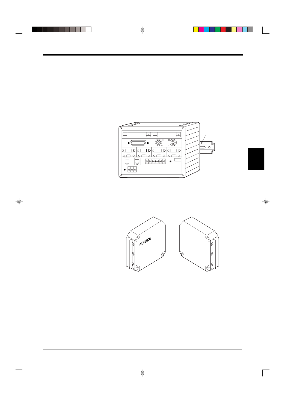
This section describes how to mount the controller (LS-5001).
Mounting the LS-5001
The LS-5001 can be mounted to a DIN rail.
Hook the upper claw first, and then press the controller against the DIN rail until it
clicks.
DIN rail
Mounting the Scanning Head Front Protection Cover (For LS-5121)
Application example of front protection cover
The LS-5121 transmitter and receiver come with a protection cover for the scan-
ning head.
Mount the cover as shown in order to prevent the front glass of the scanning head
from being scratched or broken.
Receiver
LS-5121T
SCANNING AREA
LS-5121R
SCANNING AREA
Transmitter
See also other documents in the category KEYENCE Sensors:
- LR-TB2000 Series (12 pages)
- LR-TB5000 Series (12 pages)
- LR-ZB250AN/AP (4 pages)
- LR-ZB250AN/P (3 pages)
- LR-ZBxN/P Series (3 pages)
- LR-ZBxxB (3 pages)
- OP-85135 (1 page)
- PZ-G Series (2 pages)
- PZ-V/M (2 pages)
- PS-N10 Series (12 pages)
- PX-10 (10 pages)
- CZ-V21A(P) (10 pages)
- CZ-K1(P) (8 pages)
- CZ-V1 (8 pages)
- FS-N10 Series (116 pages)
- FS-N10 Series (6 pages)
- FS-N15CN (1 page)
- FU-93(Z) (2 pages)
- FU-V Series (2 pages)
- FS-V30 (6 pages)
- FU-A40 (1 page)
- NU/FS-N Series (16 pages)
- FS-V33(P) (8 pages)
- FS-V21 (4 pages)
- FS-V22 (4 pages)
- FS-V11(P) (4 pages)
- FS-V1(P) (4 pages)
- LV-N10 Series (12 pages)
- LV-N10 Series (112 pages)
- LV-S62 (1 page)
- OP-84350 (1 page)
- LV-SA (10 pages)
- LV-SB (12 pages)
- OP-87305 (1 page)
- LV Series (10 pages)
- LV-B102 (1 page)
- EV-108M(U) (1 page)
- EZ Series (1 page)
- EM Series (1 page)
- ES-M1(P) (3 pages)
- EX-V Series (120 pages)
- EX-500(W) Series (16 pages)
- GV Series (10 pages)
- IA Series (8 pages)
- LB-1000(W) (24 pages)