1 area/segment/edge, 2 normal mode – KEYENCE LS-5000 User Manual
Page 28
Chapter 5 Outline of Measurements
22
5
5.1
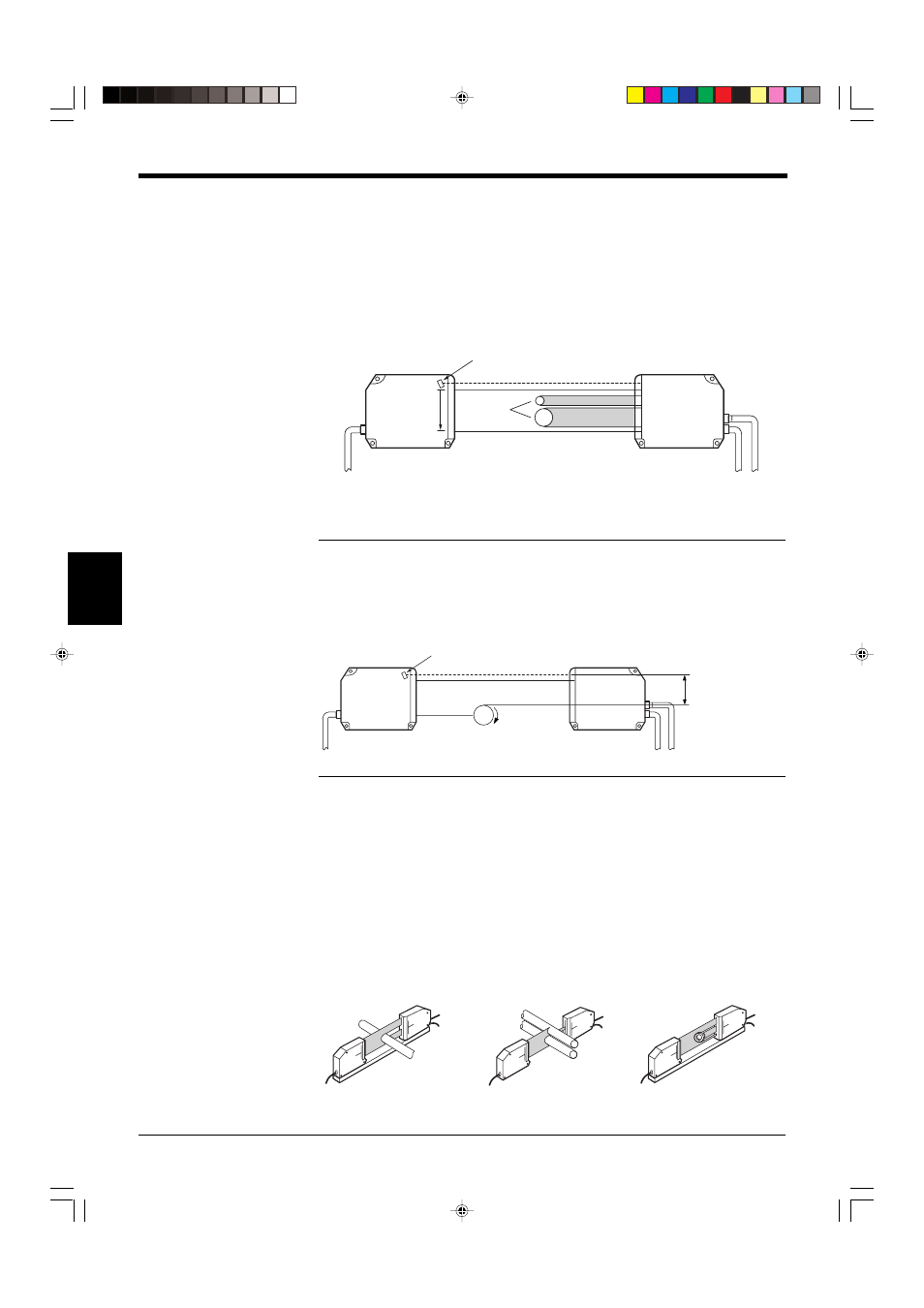
Area/Segment/Edge
When a target is placed in the measuring area, there are areas where the laser
beam is received (laser beam enters the receiver), and where the laser beam is
interrupted by the target (shadow of the target is projected on the receiver). The
border between the light and dark areas is called “EDGE”. Each section divided by
the edge is called a “SEGMENT”. The measurement "AREA" is determined by two
edges and includes all "SEGMENTS" between these two edges.
*
The edge number is counted in the laser scanning direction starting at T.EDGE
(top edge).
Note: EDGE 0
The position of the photodiode for synchronization is called “EDGE 0”.
EDGE 0 can be used as a reference point during roller oscillation measurement or
sheet edge control. (No reference edge is required.)
Example: Roller oscillation measurement
5.2
Normal Mode
➮ For the setting procedure, see p. 39.
The LS-5000 series has two measuring modes; NORMAL and PITCH. NORMAL
mode provides four types of measurement3: “DIA”, “T.EDGE (Top Edge)”,
“B.EDGE (Bottom Edge)” and “SEG(m,n)”.
The function of each mode is described below. Select the mode that suits your
measurement condition.
Edge 0
Edge 1
Edge 2
Edge 3
Edge 4
Edge 5 (n-1)
Edge 6 (n)
Photodiode for synchronization
Laser
scanning
direction
Target
Transmitter
Receiver
Photodiode for synchronization
Transmitter
Receiver
Roller
Rotating
This width can be
measured when
SEG(m,n) is set to (0,2) in
Normal mode.
DIA mode
Measurement of outer diameter
of rod or electric wire
T.EDGE/B.EDGE modes
Measurement of gap
between rollers or position
of target
edge
SEG(m,n) mode
Setting the measurement
position to measure inner
diameter using
a bearing