8 calculation setup, 88 calculation setup, Chapter 6 normal mode – KEYENCE LS-5000 User Manual
Page 47
Chapter 6 Normal Mode
41
6
8
8
8
8
8 Calculation Setup
The following calculation modes can be set for the area (A1 to A4) specified on the
AREA SETUP screen. Addition and subtraction using data of several areas can be
set.
■ Calculation for each area
OFF
: The measured value is not used for calculation.
+A#
: The measured value is output without changes.
+A#/2 : The measured value is multiplied by “1/2”.
+A#/3 : The measured value is multiplied by “1/3”.
:
–A#/4 : The measured value is multiplied by “-1/4”.
*
A# indicates either of A1 to A4.
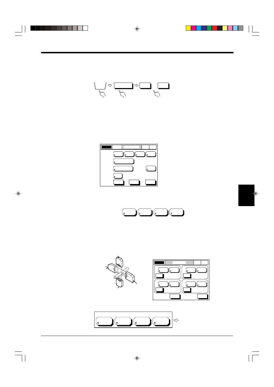
Calculation using data of several areas
Calculation setup
When the calculation modes are set as shown above, the calculation result of
“+A1+(+A2)+(-A3)” is output.
[Example 1]
When two scanning heads are installed along two axes, the average value of the
wire’s outer diameter is output.
Setting Status
1/2 of the outer diameters
measured with HEAD 1 and
HEAD 2 are added.
[AREA SETUP]
OPTIONS
OUTPUT
OUT1
• • •
OUT4
OUTPUT MODE
OUT1
LASER ON
P. 1
+A1
+A2
+A3
OFF
AREA1
AREA2
AREA3
AREA4
500
AVERAGE
CAL-
CULATE
1 (0.833ms)
MEASUR-
ING MODE
SELF-TIMING
INTERVAL (ms)
NORMAL
DIGIT
SUPPRESS
NONE
ESC
HELP
NEXT
NOR
MAL
+A1
+A2
–A3
OFF
AREA1
AREA2
AREA3
AREA4
LASER ON
AREA SETUP
NOR
MAL
P. 1
EDGEI
EDGEI
HEAD1
( 2, 3)
ESC
HELP
SET
HEAD No.
EDGE No.
A1
SEGMENT
HEAD2
( 2, 3)
SET
HEAD No.
EDGE No.
A2
SEGMENT
DIA
HEAD3
( 2, 3)
SET
HEAD No.
EDGE No.
A3
SEGMENT
DIA
HEAD4
( 2, 3)
SET
HEAD No.
EDGE No.
A4
SEGMENT
+A1/2
+A2/2
OFF
OFF
AREA1
AREA2
AREA3
AREA4