Lk-g-m-no3-e, 3 function settings, Sample-hold (trigger 2) – KEYENCE LK-G Series User Manual
Page 88
3-30
3
LK-G-M-NO3-E
3 Function Settings
■
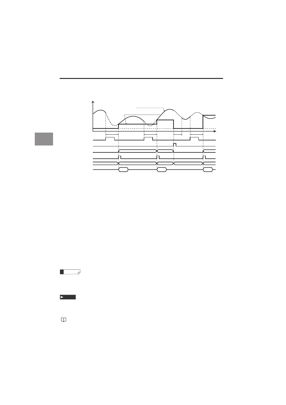
Sample-Hold (Trigger 2)
• When the TIMING input is turned on, the internal measurement value is retained and outputted. That
value is fixed by sampling the data acquired in the same number of times of averaging since the TIMING
input is on.
• In the following cases, the comparator standby status (the display shows "
------
") is displayed until
the first measured value is fixed.
When the power is turned on/when the setting is changed/when the program No. is changed/
when RESET is inputted/when auto-zero is inputted
• The comparator output is outputted according to the measurement value.
• The ON state of each output indicates the state where the NPN or PNP open-collector output is tur ned on.
• The ON state of each input indicates the state where it is short-circuited between the terminal and the
COM terminal for NPN type, and the voltage is applied between the terminal and the COM terminal for
PNP type.
• The RS-232C output is synchronized with the timing input when "Auto transmission" in the Environment
settings is set to other than OFF.
• If the TIMING input is turned on during the RESET process, the system stops the RESET process and
starts sampling.
• When the internal measurement value becomes the alarm state (measurement overrange or inadequate
light intensity), the measurement result varies depending on the settings of the alarm process.
With hold:
The measurement result is outputted by using the value immediately before the retained
value.
Without hold:
The alarm (-FFFFFF) becomes the measurement result.
• If you turn on the RESET input or the ZERO input during the sampling period, the sampling stops and the
comparator standby state is established.
• The TIMING input and RESET input can be controlled via RS-232C (page 5-8).
• The Strobe output time can be changed. Refer to "Setting the Strobe Output Time" (3-44 page) for
details.
• When the mode is set without the alarm hold, and a large value is set for the average number of times, the
measurement result may not trigger an alarm. Check the alarm output to ensure that the alarm state is
properly recognized.
• Set the filter to [Average]. [Count] can be set as desired.
Refer to "Stabilizing the Measurement by Filtering" (3-22 page) for setting the filter.
Sample-and-hold measurement value
Internal measurement value
Comparator
Measurement value
t
process
RESET
Sampling
period
ON
OFF
TIMING output
Comparator standby
(------ display)
Measurement value
ON
OFF
RESET input
ON
OFF
Comparator output
ON
OFF
Strobe output
Binary output
RS-232C output
Sampling
period
Sampling
period
Comparator
Comparator
Measurement value
Measurement value
Measurement
value
Measurement
value
Measurement
value
----------
----------
Reference
Note