Change parameter command, Change parameter command -13, Lk-g-m-no5-e – KEYENCE LK-G Series User Manual
Page 143: 5 rs-232c
5-13
5
LK-G-M-NO5-E
5 RS-232C
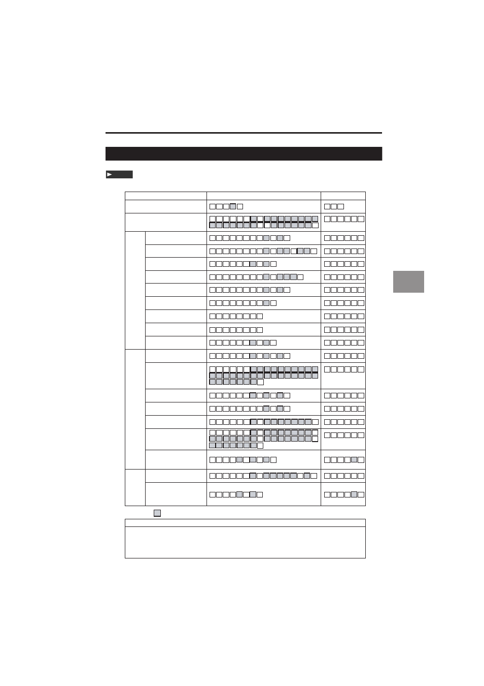
Change Parameter Command
These commands are accepted only when the controller is in the "Communication mode".
Note
Incoming command
Operation
Response command
Display panel switch
D C CR
CR
D C
,
a
Tolerance setting
S W
,
L M CR
S W
,
H A CR
S W
,
H A CR
S W
,
H B CR
S W
,
H C CR
S W
,
H C CR
S W
,
H D CR
S W
,
H D CR
S W
,
H E CR
S W
,
H D CR
S W
,
O A CR
S W
,
O B CR
S W
,
O C CR
S W
,
O E CR
S W
,
O F CR
S W
,
O H CR
S W
,
L M
,
a
,
f
f
f
f
f
f
f
,
f
f
f
f
f
f
f
,
0 f
f
f
f
f
CR
f
S W
,
O H
,
a
,
f
f
f
f
f
f
f
,
f
f
f
f
f
f
f
f
f
f
f
f
,
f
f
f
f
f
f
CR
f
S W
,
O B
,
y
,
f
f
f
f
f
f
f
,
S W
,
O F
CR
,
a
,
f
f
f
f
f
f
f
,
f
f
f
f
f
f
f
,
f
f
f
f
f
f
f
f
f
f
f
f
f
f
CR
Head
settings
OUT
settings
ABLE
ABLE control range
Measurement mode
Number of times of
alarm processing
Alarm level
Starting the ABLE
calibration
Finishing the ABLE
calibration
Mounting mode
Calculation method
Scaling
Filter
Trigger mode
Offset
Analog output
scaling
S W
,
H A
,
M
,
h
,
m CR
S W
,
H B
,
h
,
c CR
S W
,
H D
,
S
,
h CR
S W
,
O A
,
a
,
c
,
c CR
S W
,
C
I
CR
Common
settings
Data storage
S W
,
C
I
,
o
,
d
d
d
d
d
,
i
CR
S W
,
O C
,
a
,
c
,
c CR
S W
,
O e
,
a
,
c CR
S W
,
O E
,
M
,
a
,
c CR
S W
,
H D
,
P CR
S W
,
O e CR
Measurement mode,
minimum display unit,
analog-through
S W
,
C e
,
c CR
S W
,
C e CR
Sampling rate, mutual
interference prevention, timing
synchronization, comparator
output form, strobe time
S W
,
H E
,
h
,
c CR
Stopping the ABLE
calibration
S W
,
H D
,
C CR
S W
,
H A
,
R
,
h
,
x
x
,
x
x CR
S W
,
H C
,
N
,
h
,
n
n
n CR
S W
,
H C
,
L
,
h
,
c CR
Symbol
a : OUT number
c : Function No.
ddddd : Number of data
e : Function code
fffffff : Setting value
h : Head No.
i : Data interval
m : Mode
nnn : Numerical value without code
o : Data setting
p : Program No.
xx : Control range
y : OUT and head numbers
The shaded cells indicate the setting values or measurement values.
,
f
f