KEYENCE LK-G Series User Manual
Page 27
1-7
1
LK-G-M-NO1-E
1 Before Use
Operation keys
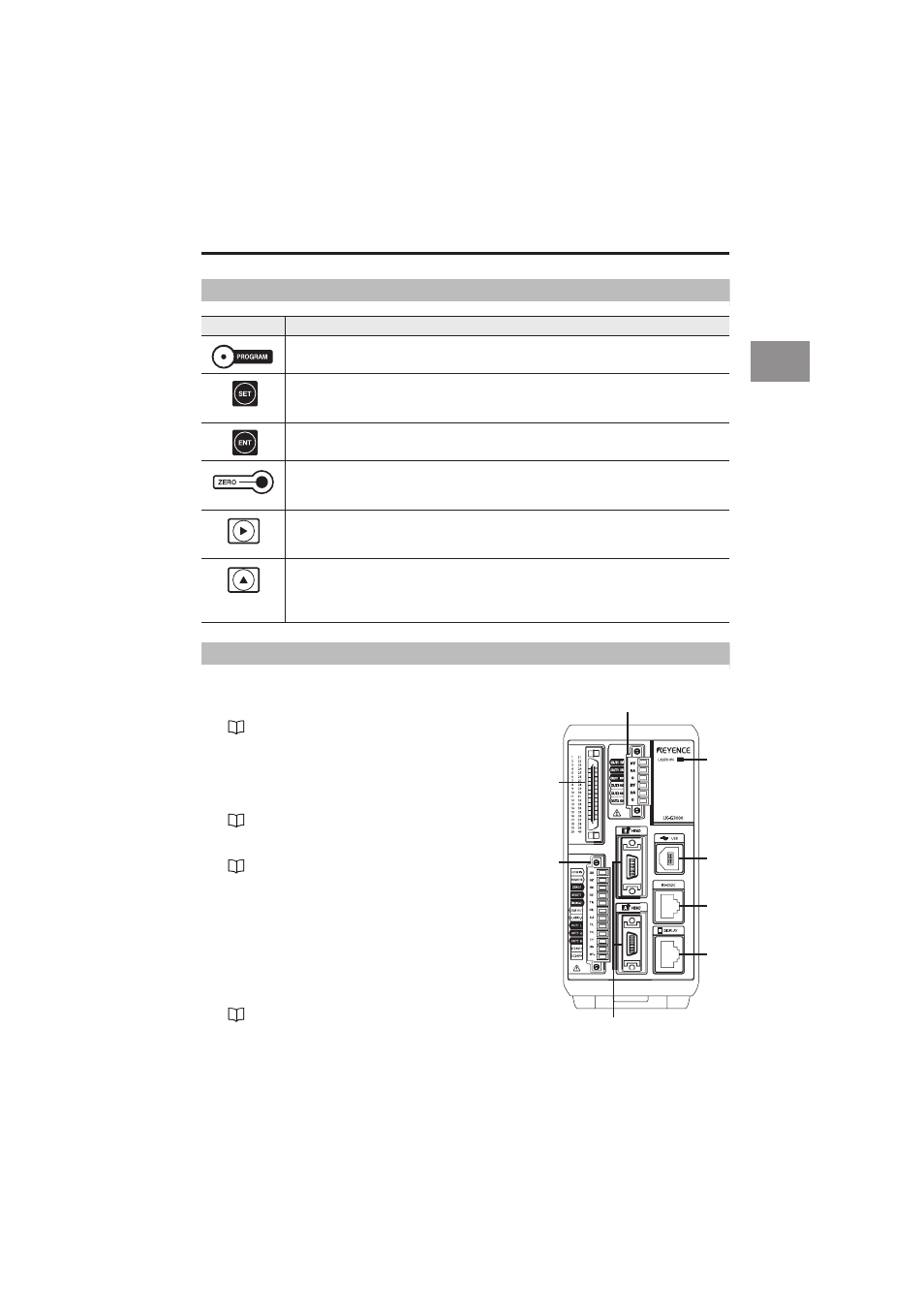
Terminal panel
1
RS-232C connector
Establishes communication with a PC or a PLC.
2
USB connector
Used when connecting the PC via USB.
Refer to "LK-Navigator User’s Manual" for details.
3
6-pin terminal block
4
Expansion connector
5
Head connectors
6
Laser emission LED.
Lights while the LK-G series operates.
7
Display panel connector
Connects the communication cable between the display
panel and the controller.
8
12-pin terminal block
Key
Function
• During measurement it calls the Program switch mode.
• During measurement it calls the Tolerance setting mode.
• When pressed for one second, it calls the Operation setting mode.
• During setting it cancels the setting content and returns to the previous setting.
• During measurement it calls the Statistics display mode.
• During setting it determines the content.
• During measurement it sets the measurement value to zero.
• When pressed for three seconds it cancels auto-zero.
• When pressed for three seconds while inputting the value, it initializes the selected item.
• During setting it switches the display to the next setting item.
• While inputting the value it shifts one digit right.
• When pressed for one second or more it shifts in higher speed.
• During measurement it changes the display for OUT1, OUT2 or both at the same time.
• During setting it switches the setting content.
• While inputting the value it switches symbols or sets numerical values.
• When pressed for one second or more it shifts in higher speed.
Refer to "Pin Layout" (page 5-2).
Refer to "6-pin I/O terminal block" (page 4-4).
Refer to "Expansion connector" (page 4-5).
Refer to "12-pin I/O terminal block" (page 4-2).
3
6
2
1
7
4
8
5