KEYENCE LK-G Series User Manual
Page 120
4-8
4
LK-G-M-NO4-E
4 Input/Output Terminals
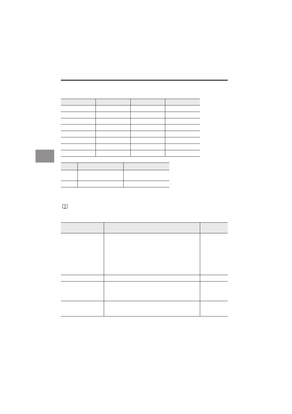
The following table shows a list of program numbers and how they relate to the status of
terminals P1 through P3 :
When you change the program number via an input/output terminal, [Setting Selection] in
the Environment settings should be changed to [Terminal Input].
Binary output
Program No.
P3
P2
P1
0
OFF
OFF
OFF
1
OFF
OFF
ON
2
OFF
ON
OFF
3
OFF
ON
ON
4
ON
OFF
OFF
5
ON
OFF
ON
6
ON
ON
OFF
7
ON
ON
ON
S
tatus
NPN type
PNP type
ON
Short-circuit state with the
COM terminal
State of voltage applied
OFF
Open state
Open state
Refer to "Setting the Program Switching Method" (page 3-50) for details.
Name
Description
Reference
page
Binary output
Outputs the measured value as binary data.
Outputs two’s complement in 21 bits.
Negative logic (1 when the NPN or PNP open-collector
output is ON)
Comparator standby status (all digits have a negative
(–) sign)
: 0x100000
Over range at positive side
: 0xOFFFFF
Over range at negative side
: 0x100000
Alarm
: 0x100000
Page 4-6
STROBE output
Strobe output of the binary output
Page 4-6
OUT1/OUT2 OUT output You can identify through which OUT number the data is
currently being output.
OFF: OUT1
ON: OUT2
Page 4-6
OUT1/OUT2 SEL input
Select the OUT number to output in binary.
OFF: OUT1
ON: OUT2
Page 4-6