KEYENCE LK-G Series User Manual
Page 144
5-14
5
LK-G-M-NO5-E
5 RS-232C
Command details
This section describes the details of the incoming commands and the response com-
mands that are sent when the incoming commands are properly processed.
■
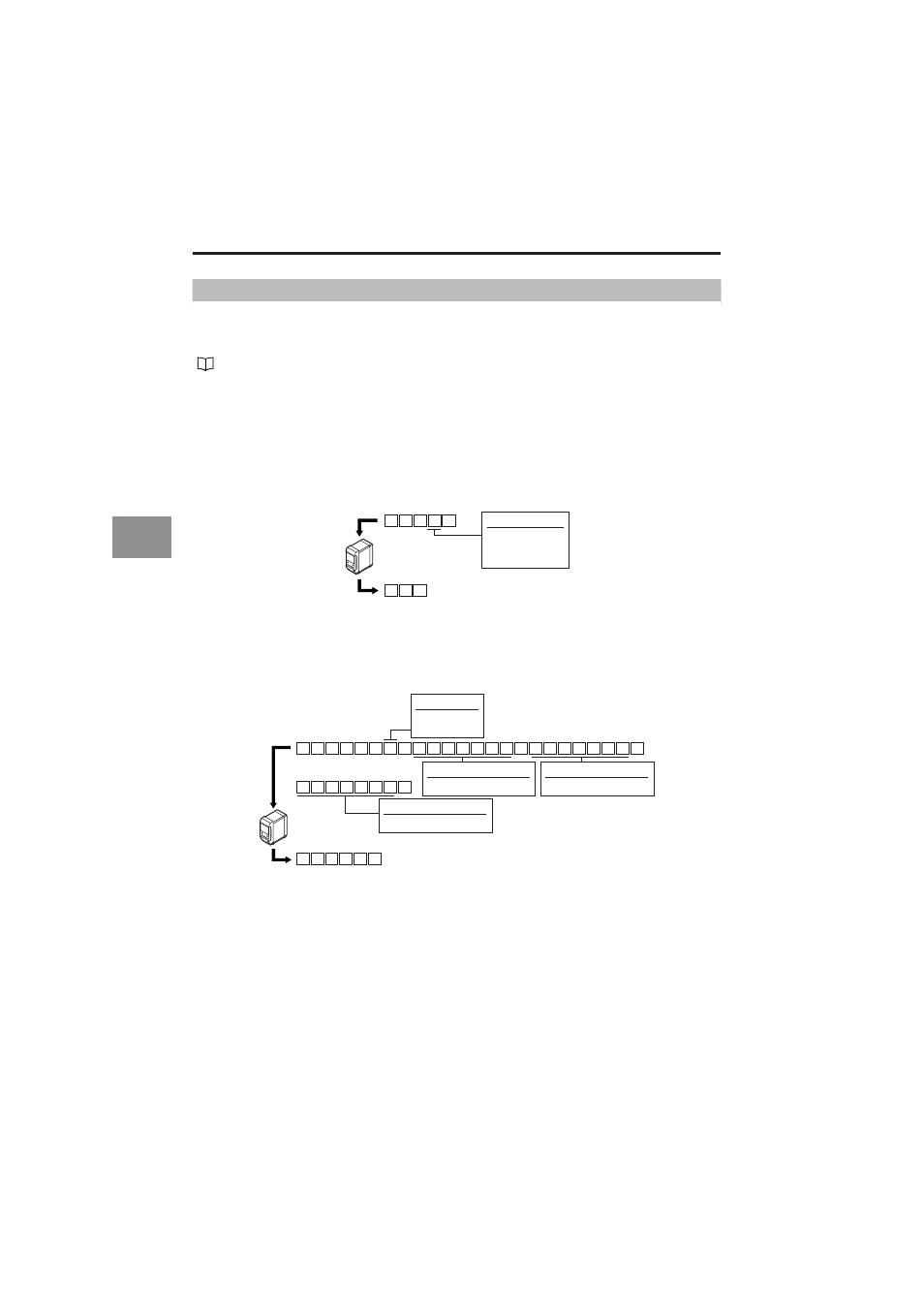
Display panel switch
Switches the content displayed on the display panel.
■
Tolerance setting
Sets the tolerance.
* The head of the hysteresis is not a character but "0" (zero).
" (page 5-5) for the error response command.
Refer to "Timing Chart" (page 5-21) for the response delay time of the response
command.
Incoming command
Response command
CR
D C
D C ,
CR
a
OUT
number
0 : OUT1+OUT2
1 : OUT1
2 : OUT2
Incoming command
Response command
S
M
L
W ,
S W ,
L M ,
a ,
f
f
f
f
f
f
f ,
f
f
f
f
f
f
f ,
0 f
f
f
f
f
f
CR
CR
Upper limit
Setting value format
Hysteresis
Setting value format
Lower limit
Setting value format
OUT
number
1 : OUT1
2 : OUT2
- LR-TB2000 Series (12 pages)
- LR-TB5000 Series (12 pages)
- LR-ZB250AN/AP (4 pages)
- LR-ZB250AN/P (3 pages)
- LR-ZBxN/P Series (3 pages)
- LR-ZBxxB (3 pages)
- OP-85135 (1 page)
- PZ-G Series (2 pages)
- PZ-V/M (2 pages)
- PS-N10 Series (12 pages)
- PX-10 (10 pages)
- CZ-V21A(P) (10 pages)
- CZ-K1(P) (8 pages)
- CZ-V1 (8 pages)
- FS-N10 Series (116 pages)
- FS-N10 Series (6 pages)
- FS-N15CN (1 page)
- FU-93(Z) (2 pages)
- FU-V Series (2 pages)
- FS-V30 (6 pages)
- FU-A40 (1 page)
- NU/FS-N Series (16 pages)
- FS-V33(P) (8 pages)
- FS-V21 (4 pages)
- FS-V22 (4 pages)
- FS-V11(P) (4 pages)
- FS-V1(P) (4 pages)
- LV-N10 Series (12 pages)
- LV-N10 Series (112 pages)
- LV-S62 (1 page)
- OP-84350 (1 page)
- LV-SA (10 pages)
- LV-SB (12 pages)
- OP-87305 (1 page)
- LV Series (10 pages)
- LV-B102 (1 page)
- EV-108M(U) (1 page)
- EZ Series (1 page)
- EM Series (1 page)
- ES-M1(P) (3 pages)
- EX-V Series (120 pages)
- EX-500(W) Series (16 pages)
- GV Series (10 pages)
- IA Series (8 pages)
- LB-1000(W) (24 pages)