Connecting the pc or plc link unit, Outputting measurement values and, Changing settings through commands -4 – KEYENCE LK-G Series User Manual
Page 134: Connecting the pc or plc link unit5-4
5-4
5
LK-G-M-NO5-E
5 RS-232C
Outputting Measurement Values and
Changing Settings through Commands
You can import the measurement value or change the parameters of the LK-G
Series by connecting it to a PC or PLC link unit.
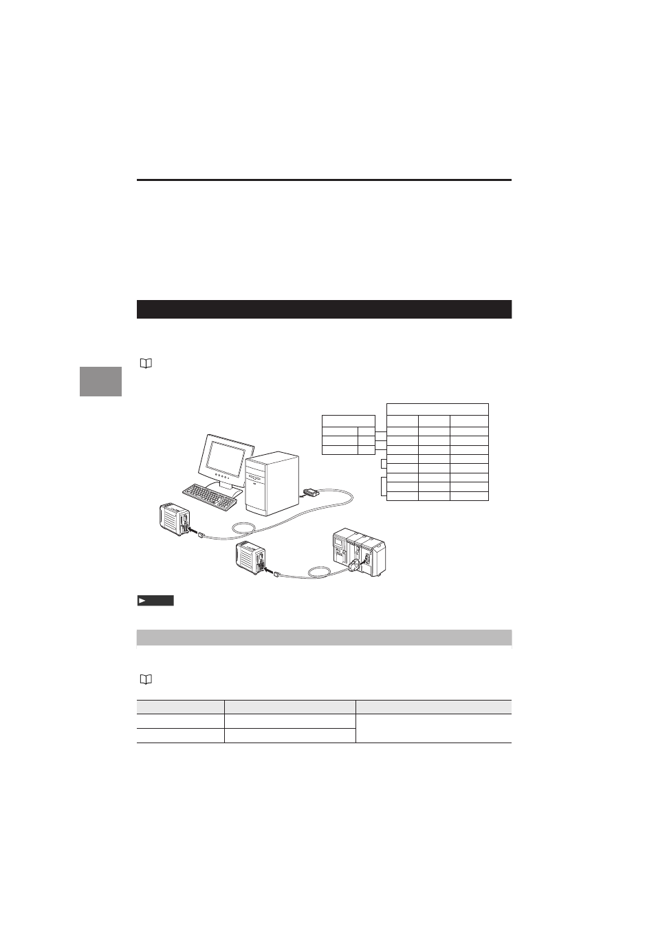
Connecting the PC or PLC Link Unit
Combine the dedicated cables OP-96368 (2.5-m straight cord), OP-26401 (D-sub 9-pin),
or OP- 96369 (D-sub 25-pin) for connection.
Connection diagram
Refer to "Precautions for Wiring" (page 4) for details.
Environment Settings Parameters
Set the functions according to the PC or PLC link unit to be connected.
Refer to the instruction manual of the PC or PLC link unit at the time of connection.
Refer to "Setting the Communication Specifications of the RS-232C" (page 3-49).
Item
Setting value
Remarks
Baud rate
9600/19200/38400/57600/115200 Set the parameter according to the
external devices to be connected.
Parity check
None/Even/Odd
RD (RXD)
SD (TXD)
e
w
RD (RXD)
w
e
SG (GND)
t
u
RS (RTS)
u
r
CS (CTS)
i
t
DR (DSR)
y
q
y
CD (DCD)
i
ER (DTR)
r
@0
t
SG (GND)
r
SD (TXD)
e
PC side
LK-G side
Signal name
OP-26401
OP-96369
PLC link unit
PC
Note