Lk-g-m-no3-e – KEYENCE LK-G Series User Manual
Page 86
3-28
3
LK-G-M-NO3-E
3 Function Settings
■
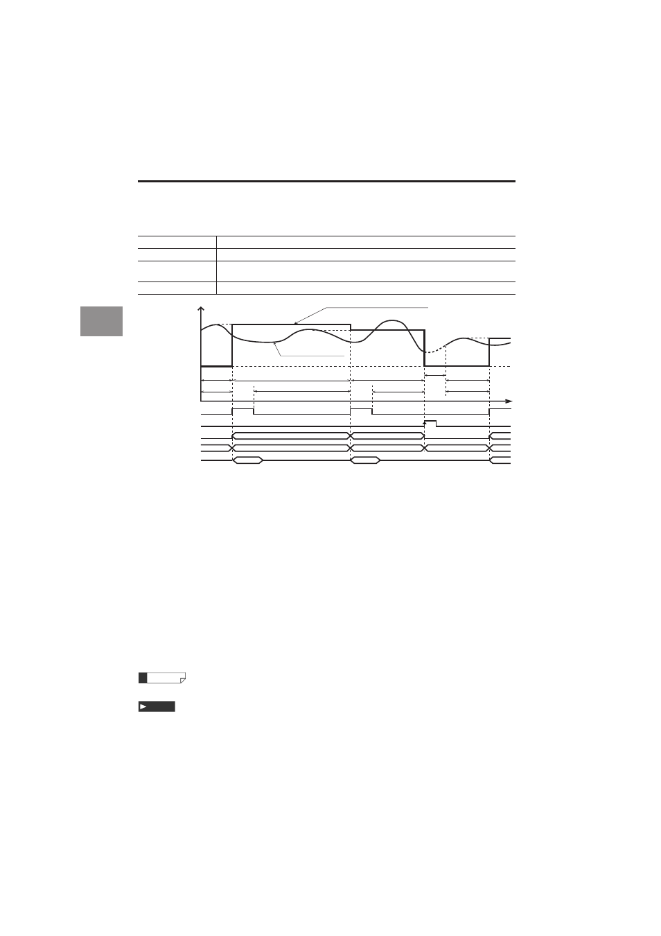
Peak hold/bottom hold/peak-to-peak hold/average hold
The values within the period of time (sampling period) determined by the external TIMING input are
measured, and the display and output are retained. The sampling period differs between Trigger 1 and 2.
•
For Trigger 1, the sampling period is between the rising edge of the TIMING input to the rising edge of the next TIMING
input. When the TIMING input turns ON, the measurement value in the sampling period immediately before
is outputted.
The RESET process is not performed when the TIMING input is turned on.
•
For Trigger 2, the sampling period is between the falling edge of the TIMING input to the rising edge of the next TIMING
input. When the TIMING input turns ON, the measurement value in the sampling period immediately before is output.
The RESET process of the internal measurement value is performed when the timing input is turned off.
• In the following cases, the comparator standby status (the display shows "
------
") is displayed until the
first measurement value is fixed. When the power is turned on/when a setting is changed/when a program
No. is changed/when RESET is inputted/when Auto-zero is inputted
• The comparator output is outputted according to the measurement value.
• The ON state of each output indicates the state where the NPN or PNP open-collector output is turned on.
• The ON state of each input indicates the state where it is short-circuited between the terminal and the COM
terminal for NPN type, and the voltage is applied between the terminal and the COM terminal for PNP type.
• The RS-232C output is synchronized with the timing input when "Auto transmission" in the Environment set-
ting is set other than OFF. (page 3-49)
• Refer to "Functions of the Input and Output Signals" (page 4-7) for details of binary output.
• If the TIMING input becomes ON during the RESET processing, the comparator standby status (the display
shows "
------
") is displayed.
• When the internal measurement value becomes the alarm state, the measurement result varies depending
on the settings of the alarm process.
With hold: The measurement result is outputted by using the value immediately before the retained value.
Without hold: The measurement value is outputted while ignoring the alarm state period at the time of peak
hold. When the whole sampling period is in the alarm state, the alarm (-FFFFFF) becomes the measure-
ment result. At the time of other than peak hold, the alarm (-FFFFFF) becomes the measurement result.
The TIMING input and RESET input can be controlled using the RS-232C (page 5-8).
• Set the average filter (the number of times for averaging) to 1 if the measurement mode is set to average hold.
• When the mode is set without the alarm hold, and a large value is set for the average number of
times, the measurement result may not trigger an alarm. Check the alarm output to ensure that the
alarm state is properly recognized.
Peak hold
Measures the maximum value within the specified period of time (sampling period).
Bottom hold
Measures the minimum value within the specified period of time (sampling period).
Peak-to-peak hold
Measures the differential value of the maximum and minimum values within the
specified period of time (sampling period).
Average hold
Measures the average value within the specified period of time (sampling period).
(e.g) Measurement value in peak-hold setting
Internal measurement value
t
Sampling
period
Sampling period
Sampling period
RESET
process
Comparator standby
(------ display)
Measurement value
Comparator
Measurement value
Measurement value
Measurement value
Measurement value
Measurement value
Measurement value
Comparator
Comparator
ON
OFF
TIMING input
ON
OFF
RESET input
ON
OFF
Comparator output
Binary output
RS-232C output
Trigger 1
Trigger 2
Sampling
period
Sampling period
Sampling
period
Sampling
period
Sampling period
--------
--------
Reference
Note