Timing chart, Lk-g-m-no3-e – KEYENCE LK-G Series User Manual
Page 85
3-27
3
LK-G-M-NO3-E
3 Function Settings
Timing Chart
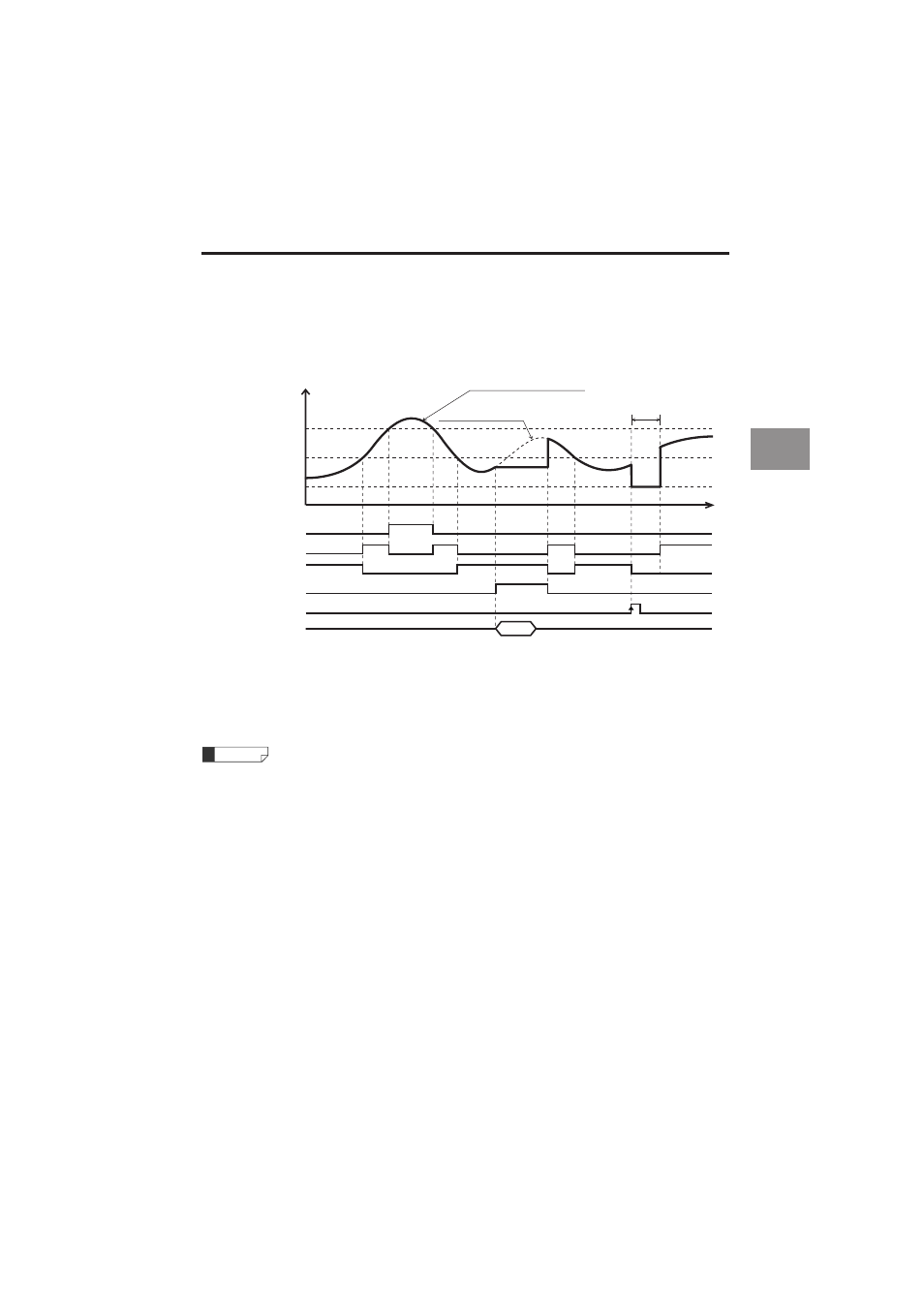
■
Normal
Measurement is performed consecutively, and the measurement value is displayed and outputted as
required.
• The ON state of each output indicates the state where the NPN or PNP open-collector output is turned on.
• The ON state of each input indicates the state where it is short-circuited between the terminal and the COM
terminal for NPN type, and the voltage is applied between the terminal and the COM terminal.
• The RS-232C output is synchronized with the timing input when "Auto transmission" in the Environment set-
ting is set other than OFF. (page 3-49)
Refer to "Functions of the Input and Output Signals" (page 4-7) for details of binar y output.
If the RESET input is set to ON when the TIMING input is ON, the comparator standby state (the dis-
play shows "
------
") is displayed until the TIMING input becomes OFF.
• The TIMING input and RESET input can be controlled using the RS-232C (page 5-8).
• There is no difference between the functions of Trigger 1 and Trigger 2.
Measurement value in Normal mode
Internal measurement value
ON
OFF
HI output
t
Comparator standby
(------ display)
HI set value
Measurement value
LO set value
ON
OFF
GO output
ON
OFF
LO output
ON
OFF
TIMING output
ON
OFF
RESET input
RS-232C output
Measurement
value
RESET process
Reference