Identifying part names and functions, Controller, Identifying part names and functions -6 – KEYENCE LK-G Series User Manual
Page 26: Controller -6
1-6
1
LK-G-M-NO1-E
1 Before Use
Identifying Part Names and Functions
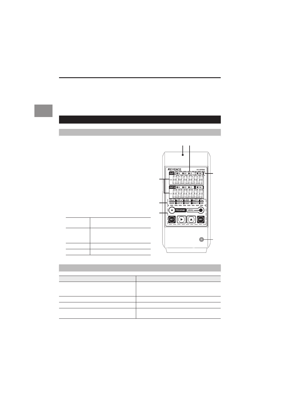
This section describes the name and function of each part.
Controller
Display panel
1
Display panel fixing case
2
Display panel fixing screw
3
Measurement value indicators
Display the measurement value, tolerance
comparator value, and various statistical results.
The setting items are displayed during setting.
Green: Within the tolerance Red: Outside the tolerance
4
Comparator output indicator
Lights during the comparator output (HI, GO, or LO).
5
Timing input indicator
Lights when the timing signal is being input.
6
Head status display indicator
Displays the laser emission status and the
measurement status.
7
Operation keys
Displays and descriptions of the measurement value indication
LASER ON
Laser emission LED. Lights while
the LK-G Series is in operation.
STABILITY
Lights in green or orange within the
measurement range. Lights in red outside
the measurement range, alarm, or laser-off.
BRIGHT
Lights at the exceeding light intensity alarm.
DARK
Lights at the light intensity shortage alarm.
Display
Description
Numerical value (±999999)
Displays the measurement result in numerical value.
The display unit, decimal point position, and minimum
display unit vary depending on the settings.
FFFFFF (HI output: ON. Monitor output: + 10.8 V)
Displayed when the value exceeds the display range.
–FFFFFF (LO output: ON. Monitor output: –10.8 V)
Displayed when the value drops below the display range.
- - - - - -
(HI, GO and LO outputs: OFF. Monitor output: –10.8 V)
Displayed during the comparator standby state.
1
4
5
2
7
6
3