KEYENCE LK-G Series User Manual
Page 116
4-4
4
LK-G-M-NO4-E
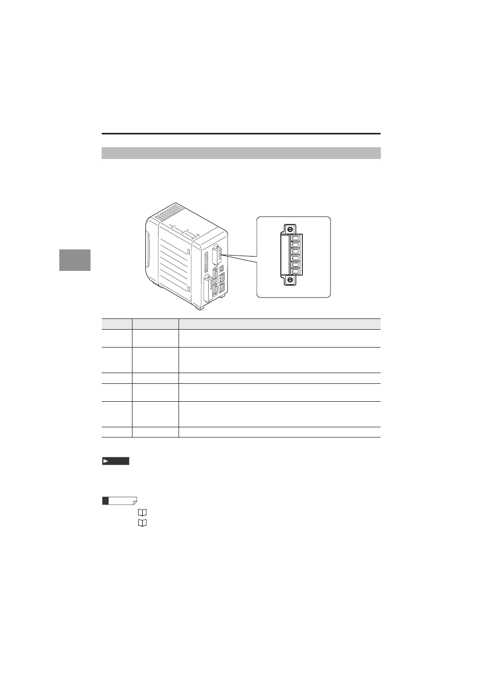
4 Input/Output Terminals
6-pin I/O terminal block
Used for the analog monitor output.
Matching cable specification: AWG28 to 16, Approximately 6.5mm of the insulation should be
striped from the cable.
*0 V of pin Nos. 1 and 4 are common.
24 V DC (–) for the 12-pin I/O terminal block and 0 V are common via a choke coil. Be
careful not to generate a potential difference.
•Refer to
page 4-10 for the electrical specifications.
•Refer to
page 3-34 for the scaling procedures of the analog output.
Pin No.
Signal name
Description
6
OUT1 (V)
Analog voltage output of OUT1
Outputted in the range of ±10.8 V with reference to the displayed value.
5
OUT1 (A)
Analog current output of OUT1
Outputted in the range of 3.36 mA to 20.64 mA with reference to the
displayed value.
4
OUT1 0V
0V terminal for OUT1
3
OUT2 (V)
Analog voltage output of OUT2
Outputted in the range of ±10.8 V with reference to the displayed value.
2
OUT2 (A)
Analog current output of OUT2
Outputted in the range of 3.36 mA to 20.64 mA with reference to the
displayed value.
1
OUT2 0V
0V terminal for OUT2
1
2
3
4
5
6
Note
Reference