KEYENCE LK-G Series User Manual
Page 118
4-6
4
LK-G-M-NO4-E
4 Input/Output Terminals
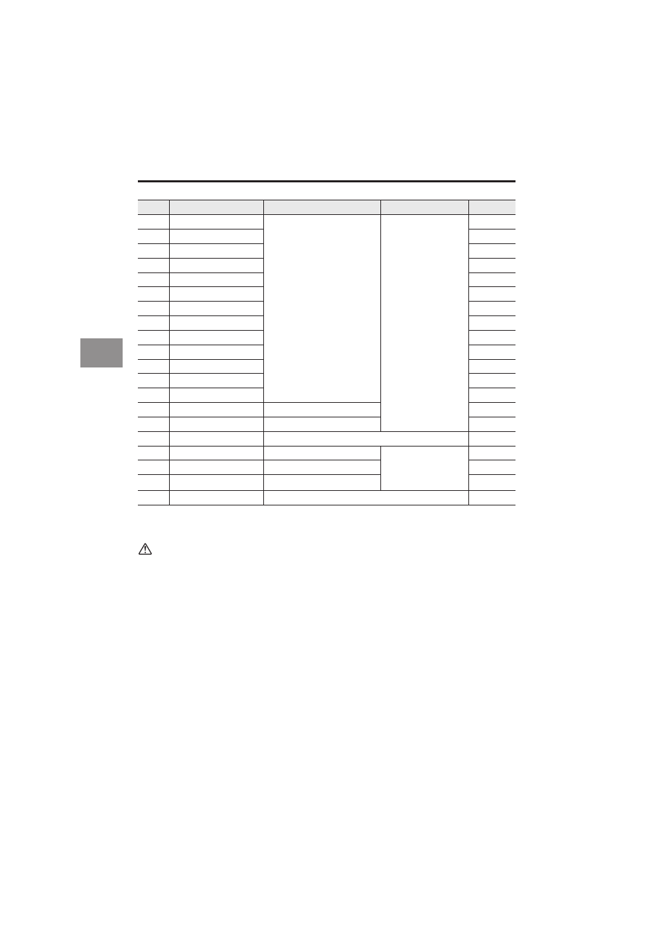
* COMs for output of pin Nos. 5 and 36 are common.
* COMs for input of pin Nos. 12 and 40 are common.
* The cord color is the wire color of the extension connector cable (OP-51657).
Caution
• Precautions for Wiring
Part of each input/output circuit of the LK-G Series is internally common. Be sure that no
potential difference is generated between the common terminals due to the potential dif-
ference between wires or external devices.
Refer to "Precautions for Wiring" page 4 for details.
• NPN type
COM OUT and COM IN are common via a choke coil. Also, 24 V DC (–), COM OUT and
COM IN of the 12-pin I/O terminal block are all common via a choke coil. Be careful not to
generate a potential difference.
• PNP type
COM IN and 24 V DC (-) are common via a choke coil. Also, 24 V DC (-), and COM IN of
the 12-pin I/O terminal are common via a choke coil. Be careful not to generate a potential
difference.COM OUT and COM OUT of the 12-pin I/O terminal are common.
21
Binary (8)
Binary output
NPN open-collector
output (NPN type)
PNP open-collector
output (PNP type)
Brown
22
Binary (9)
Red
23
Binary (10)
Orange
24
Binary (11)
Yellow
25
Binary (12)
Green
26
Binary (13)
Blue
27
Binary (14)
Purple
28
Binary (15)
Gray
29
Binary (16)
White
30
Binary (17)
Black
31
Binary (18)
Brown
32
Binary (19)
Red
33
Binary (20) (MSB)
Orange
34
STROBE
STROBE output
Yellow
35
OUT1/OUT2 OUT
OUT1/OUT2 selection output
Green
36
COM OUT
COM for output
Blue
37
OUT1/OUT2 SEL
OUT1/OUT2 selection input
Non-voltage input
(NPN type)
Voltage input
(PNP type)
Purple
38
LASER OFF A
LASER OFF A input
Gray
39
LASER OFF B
LASER OFF B input
White
40
COM IN
COM for I/O
Black
Pin No.
Signal name
Description
Cord color