2 link structure and control – Cub Cadet 8404 User Manual
Page 97
CLUTCH
3-9
D615-W02 May-2003
615W320A
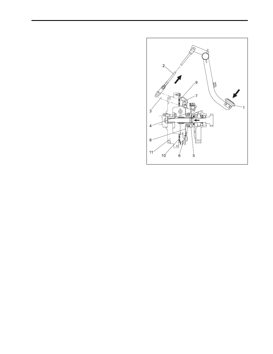
2.2 LINK STRUCTURE AND CONTROL
•
If working clutch pedal, clutch rod (2) is pulled in the
direction of arrow and release hub (5) moves to the
direction of arrow through release fork (4).
•
Release bearing (6) of release hub pushes dia-
phragm spring (8) of clutch cover assembly (7), re-
leases clutch disc (10) between clutch pressure
plate (9) and flywheel (11), and then disconnects
power from engine.
(1) Clutch Pedal
(2) Clutch Rod
(3) Main Clutch Lever
(4) Clutch Release Fork
(5) Clutch Release Hub
(6) Release Bearing
(7) Clutch Cover Assembly
(8) Diaphragm Spring
(9) Pressure Plate
(10) Clutch Disc
(11) Flywheel
This manual is related to the following products: