Cub Cadet 8404 User Manual
Page 122
CHAPTER 4 8354/8404
4-18
D615-W02 May-2003
615W433A
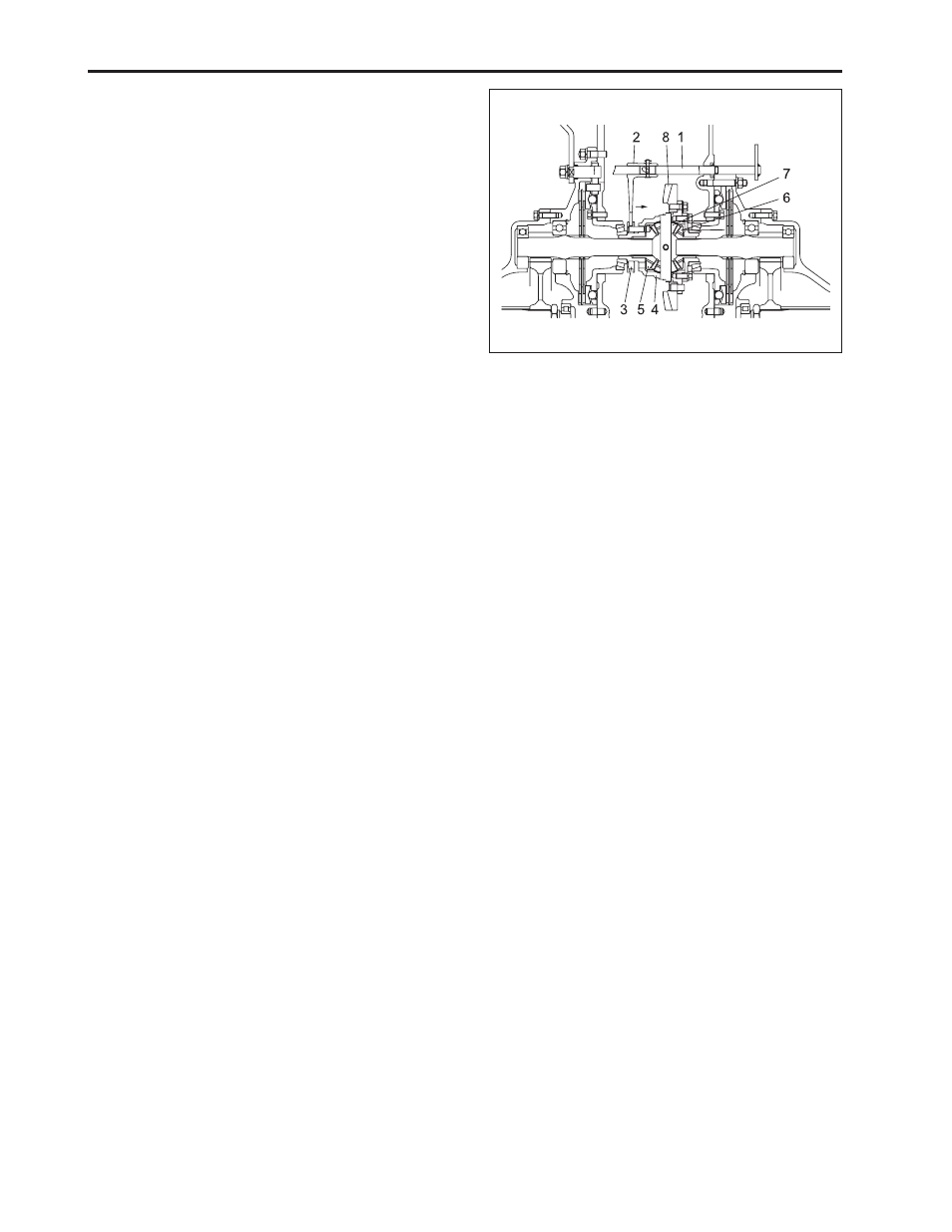
(1) Differential Locking Fork Shaft
(2) Differential Locking Fork
(3) Differential Locking Shift
(4) Differential Gear Case
(5) Differential Side Gear (Left)
(6) Differential Side Gear (Right)
(7) Differential Pinion
(8) Spiral Bevel Gear
C. Differential Lock
•
When the resistance of the right and left tires varies
from the ground or work conditions, it could cause
the wheels to slip and one wheel will be rotating
faster than the other. Therefore, towing power will
be decreased. To compensate for this, the differen-
tial locking device restricts differential function and
provides equal rpm’s to both wheels.
•
If working the differential locking pedal, differential
locking fork shaft (1) will rotate and the differential
locking fork (2) will moved to differential side gear
(5) with differential locking shift (3), pin of shift en-
tered groove of side gear to lock side gear. Rotation
of spiral bevel gear (8) will be transmitted to both
wheels to move tractors forward.
•
If stopping differential locking pedal, differential lock-
ing shift (3) will be removed from side gear by the
return spring of the differential locking pedal to re-
lease locking and to return differential function.