Gear pump – Cub Cadet 8404 User Manual
Page 215
STEERING SYSTEM
8-5
D615-W02 May-2003
615W804A
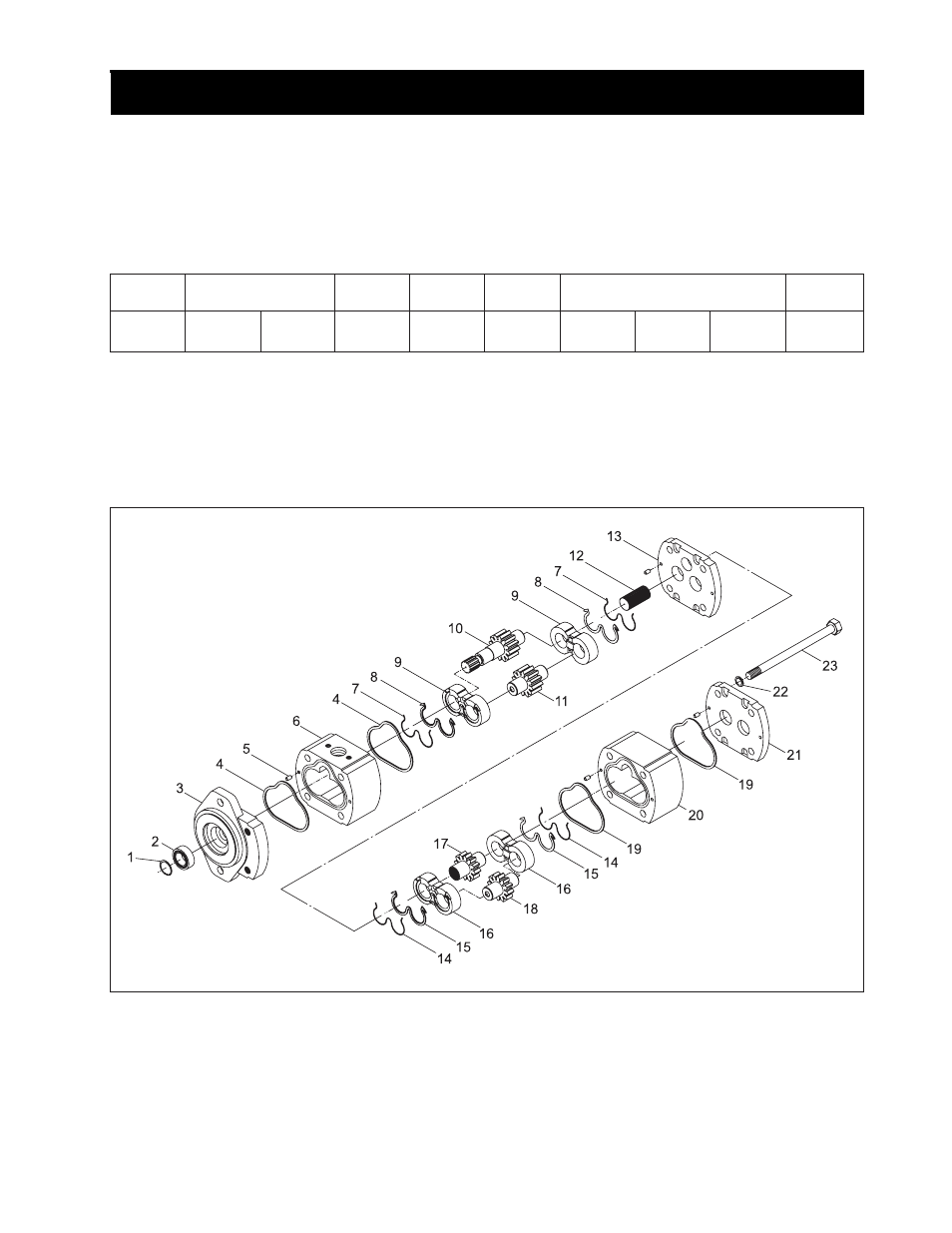
3.3 STRUCTURE OF GEAR PUMP
(1) Snap Ring
(2) Bearing
(3) Cover (Front)
(4) Seal Ring
(5) Pin
(6) First Pump
(7) Seal Ring
(8) Seal Ring
(9) Bushing
(10) Drive Gear Shaft 1
(11) Passive Gear 1
(12) Coupling
(13) Cover
(14) Seal Ring
(15) Seal Ring
(16) Bushing
(17) Drive Gear Shaft 2
(18) Passive Gear
(19) Seal Ring
(20) Second Pump
(21) Cover
(22) Spring Washer
(23) Bolt
3.1 PUMP CHARACTERISTICS
The power steering hydraulic pumps use the pump hav-
ing superior volume efficiency and mechanical efficiency
to extract power from engines right cam shaft gear.
3.2 MAJOR SPECIFICATION
Type
Tandem
Volume (cc/rev)
12 First
7.2
Second
Gear
ratio
1 : 0.9
Rotation
direction
C.C.W
RPM
range
~ 3515
Discharge flow rate in engine
rated rotation (l/min, gal/min)
Q1: 29.7
7.86
Q2: 17.8
4.71
Qt: 47.5
12.57
Attached
position
Right of
engine
•
Ref.) Q1: For hydraulic elevation (First)
Q2: Steering cylinder (Second)
Qt: Total discharge flow rate
C.C.W: Count clock wise.
3. GEAR PUMP