Cub Cadet 8404 User Manual
Page 229
STEERING SYSTEM
8-19
D615-W02 May-2003
615W828A
615W829A
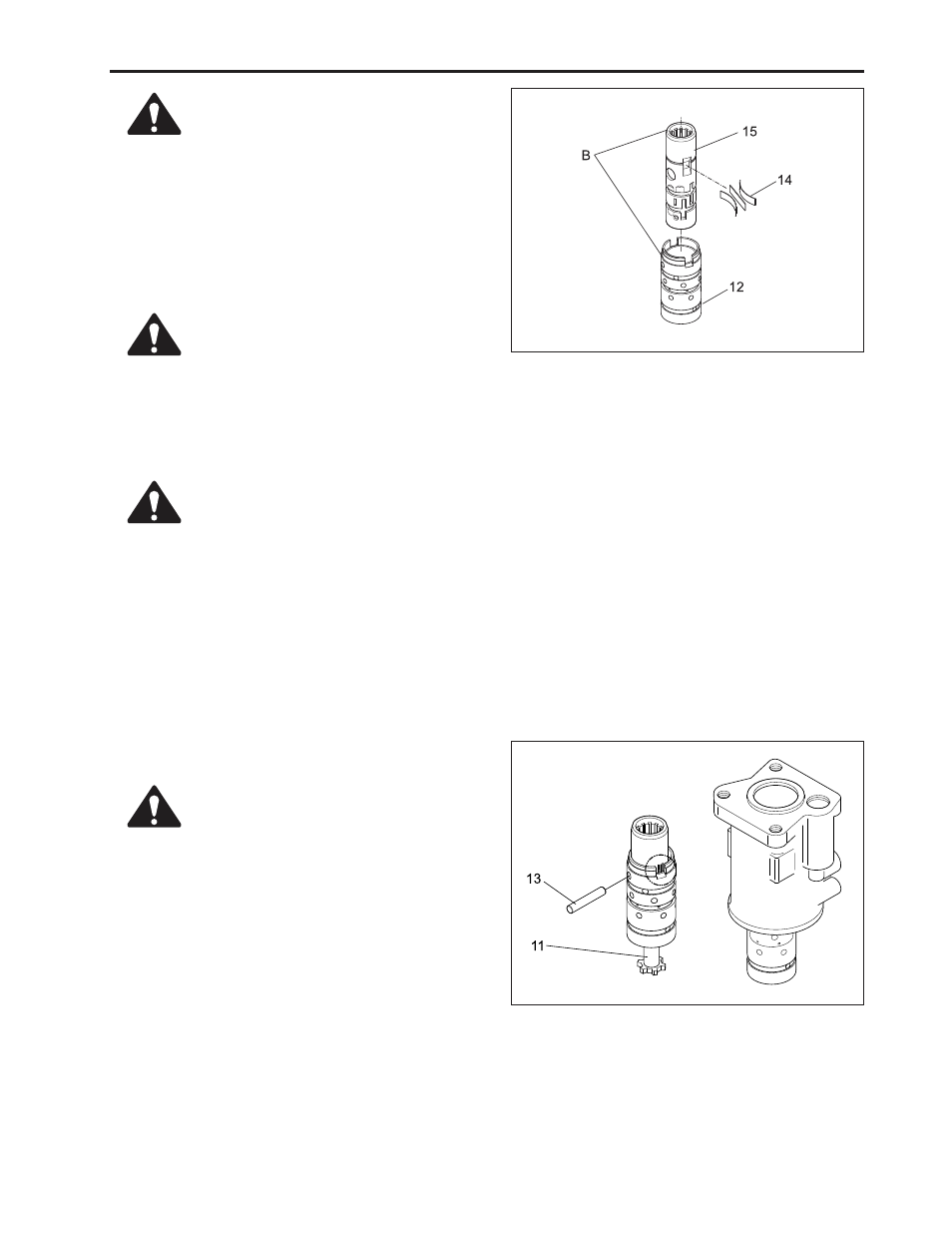
5. While raising spool and from sleeve and com-
pressing the opposite end of centering spring by
hand, push spool into the groove of sleeve. This
time, slide insert tool at the same speed of spring
compression. After inserting, align the end of
spring with outer circumference of sleeve.
11. Apply screw (1) with oil and insert into end cap (2).
(11) Driver
(13) Pin
•
Align with position alignment mark
when disassembling.
•
Centering spring can be protruded
from spool, so always wear safety
goggle.
CAUTION
•
Make sure that spool and sleeve as-
sembly are rotated slightly in housing.
CAUTION
6. Insert pin (13) into hole of sleeve and spool and
sleeve assembly into GEROTOR of housing.
7. Insert driver (11). This time, align with pin (13) and
yoke of driver.
8. Assemble O-ring (31) on gerotor and assemble
GEROTOR rotor into groove.
9. Insert plate (5), O-ring (6) and plate (7) into inside
spline of GEROTOR rotor.
10. Align bolt hole of housing with oil hole using spacer
plate (8).
•
Make sure the number of centering
spring is correct, as it is different as
input torque spec. of the product.
CAUTION
•
Tighten seven screws (1) into about 1.
0 Kgf·m (9.8 N·m, 7.2 lbf·ft) torque in
advance.
CAUTION
(12) Sleeve
(15) Spool
(14) Spring
[B] Position Alignment Mark