Cub Cadet 8404 User Manual
Page 253
HYDRAULIC SYSTEM
9-19
D615-W03 May-2003
615W922B
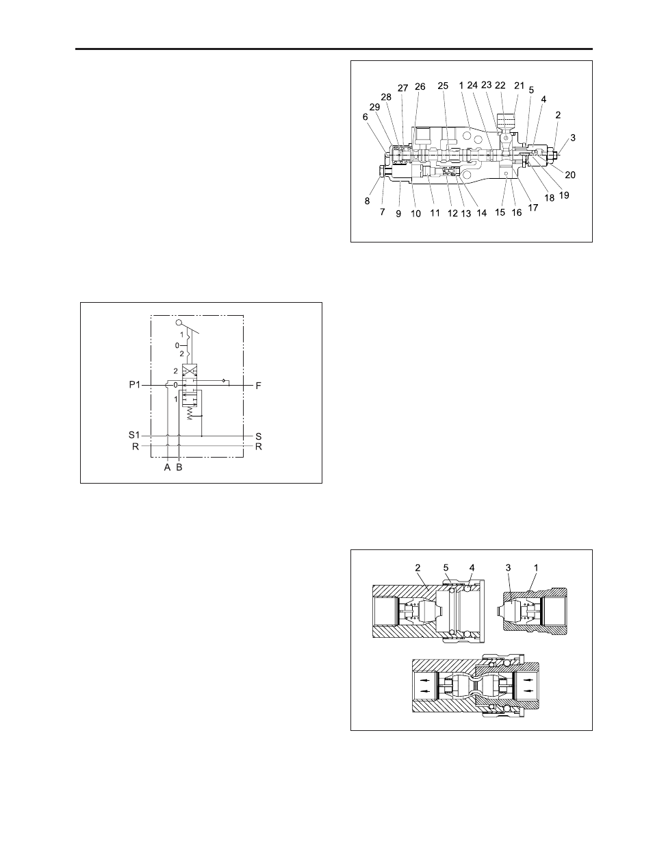
10.2 ACTING VALVE
A. Operation principle
A double acting detent type auxiliary control valve is
used, and the construction is shown in the figure right.
When the auxiliary control valve operating lever is moved
to the implement cylinder actuating position, the spool
is moved and the oil from the pump port flows into A to
B, causing the implement cylinder to operate.
The return oil from the implement cylinder flows out of
the tank port through A of B and returns to the transmis-
sion case.
This type is equipped with a special non-return valve
which ensures that oil under pressure is held where
required. This guarantees that implements will be held
at a steady height which no change of lowering.
B. Circuit diagram
615W923A
10.3 QUICK COUPLER
(1) Coupler Socket (Male)
(4) Ball
(2) Coupler Socket (Female)
(5) Sleeve
(3) Pocket
615W947B
(1) Body
(17) Elastic Pin
(2) Nut
(18) Plug
(3) Screw
(19) O-Ring
(4) Cover
(20) Spring
(5) Nut
(21) Ball
(6) O-Ring
(22) Ball
(7) O-Ring
(23) Articulation
(8) Screw
(24) Pin
(9) Washer
(25) Seal Ring
(10) Screw
(26) O-Ring
(11) Cover
(27) Pilot Spool
(12) Seal Cover
(28) Washer
(13) Valve Seat
(29) Spring
(14) Spring
(30) Screw
(15) Valve
(31) Spacer
(16) Valve Seat