Disassembly, maintenance – Cub Cadet 8404 User Manual
Page 222
CHAPTER 8 8354/8404
8-12
D615-W02 May-2003
615W814A
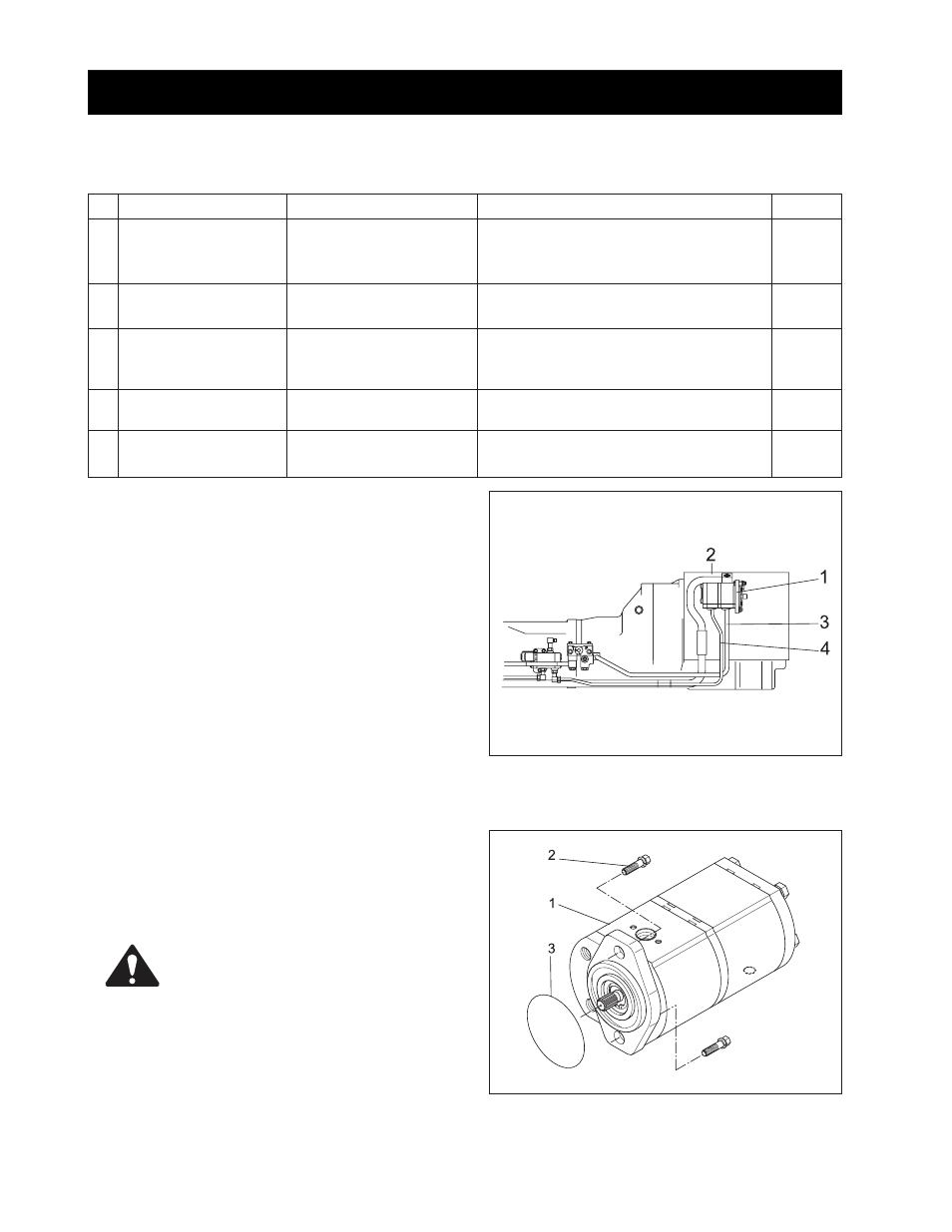
1. Disassemble bolt (2).
2. Detach gear pump (1).
3. Detach O-ring (3)
- See assembly bolt spec (M10*P1.25).
(1) Gear Pump Assembly (3) O-Ring
(2) Bolt
•
Make sure O-ring not damaged and if
broken, replace it.
CAUTION
615W813A
8.1 GEAR PUMP
A. Tightening Torques
No.
1
2
3
4
5
Item
Clearance between
drive gear and body
Drive shaft worn
Clearance between
drive shaft and bushing
Length of bushing
Length between pump
body and mm bushing
Reference Value
Allowable
limit: 0.05 mm (0.002 in.)
Allowable
limit: 19.25 mm (0.758 in.)
Allowable
limit: 0.177 mm (0.007 in.)
Allowable
limit: 25.75 mm (1.014 in.)
0.10 ~ 0.18 (0.004 ~ 0.007)
(bushing short)
Description
- Assemble bushing into body.
- Assemble drive shaft with idle gear.
- Measure using clearance gage.
- Measure shaft diameter using
micrometer.
- Measure bushing I.D. using micrometer.
- Compare th difference from measured
drive shaft diameter.
- Measure the length of bushing using
micrometer
- Measure bushing and pump body using
micrometer.
Number
-
-
-
-
-
B. Disassembly and Assembly
a. Disconnection of Gear Pump
Disassembly hydraulic pipe (3), PTO hydraulic pipe (4),
and intake pipe 3 (2) from gear pump assembly (1).
(1) Gear Pump Assembly (3) Hydraulic Pipe 1
(2) Intake Pipe 3
(4) PTO Hydraulic Pipe
8. DISASSEMBLY, MAINTENANCE