Cub Cadet 8404 User Manual
Page 65
ENGINE SYSTEM
2-43
D615-W02 May-2003
615W281A
615W280A
615W279A
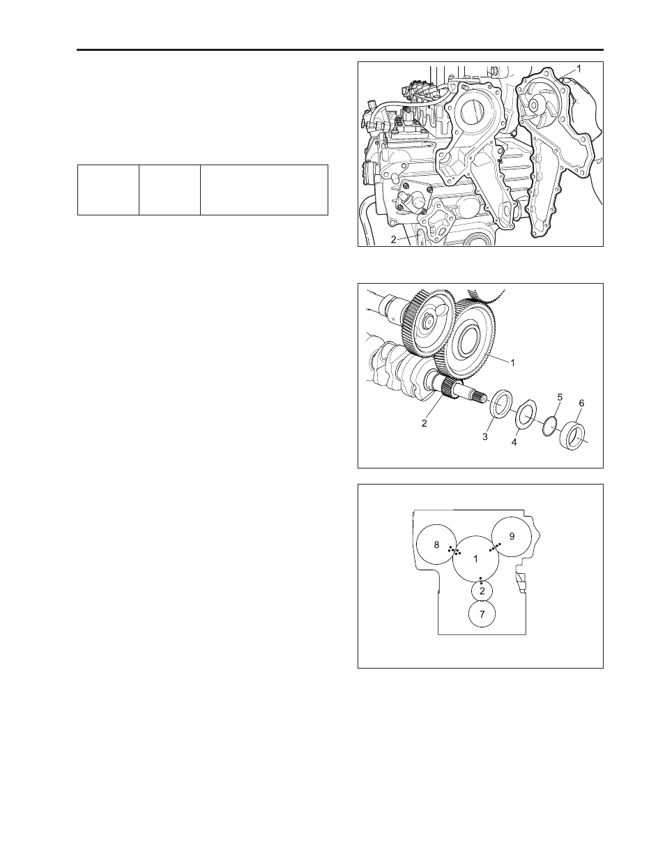
(F) Water pump and relief valve
1. Remove the water pump body (1).
2. Remove the relief valve cover (2) and take out the
ball, spring and seat.
(When reassembling)
•
Install the relief valve cover (2) with its mark up.
(G)
Idle gear and crank gear
1. Remove the crankshaft collar (6), O-ring (5), oil
slinger (4) and crank gear collar (3) in the order.
2. Remove the idle gear (1).
3. Remove the crankshaft gear (2) with a special use
puller set.
(When reassembling)
•
Heat the crankshaft gear to approx. 80 °C (176 °F)
and insert the crankshaft.
•
Apply oil to the O-ring (5).
Tightening
torque
Relief valve
cover screw
32.4 ~ 36.3 N·m
3.3 ~ 3.7 kgf·m
23.9 ~ 26.8 lbf·ft
(1) Water Pump Body
(2) Relief Valve Cover
IMPORTANT:
•
Install the idle gear, aligning the alignment marks
referring to the figure.
(1) Idle Gear
(6) Crankshaft Collar
(2) Crankshaft Gear
(7) Oil Pump Gear
(3) Crank Gear Collar
(8) Injection Pump Gear
(4) Oil Slinger
(9) Cam Gear
(5) O-Ring