Cub Cadet 8404 User Manual
Page 204
CHAPTER 7 8354/8404
7-16
D615-W03 May-2003
615W724A
615W725A
Sect.
Spec.
Tightening torque
The attaching bolt of
center pin
M12
77.5 ~ 90.2 N·m
7.9 ~ 9.2 kgf·m
57.2 ~ 66.5 lbf·ft
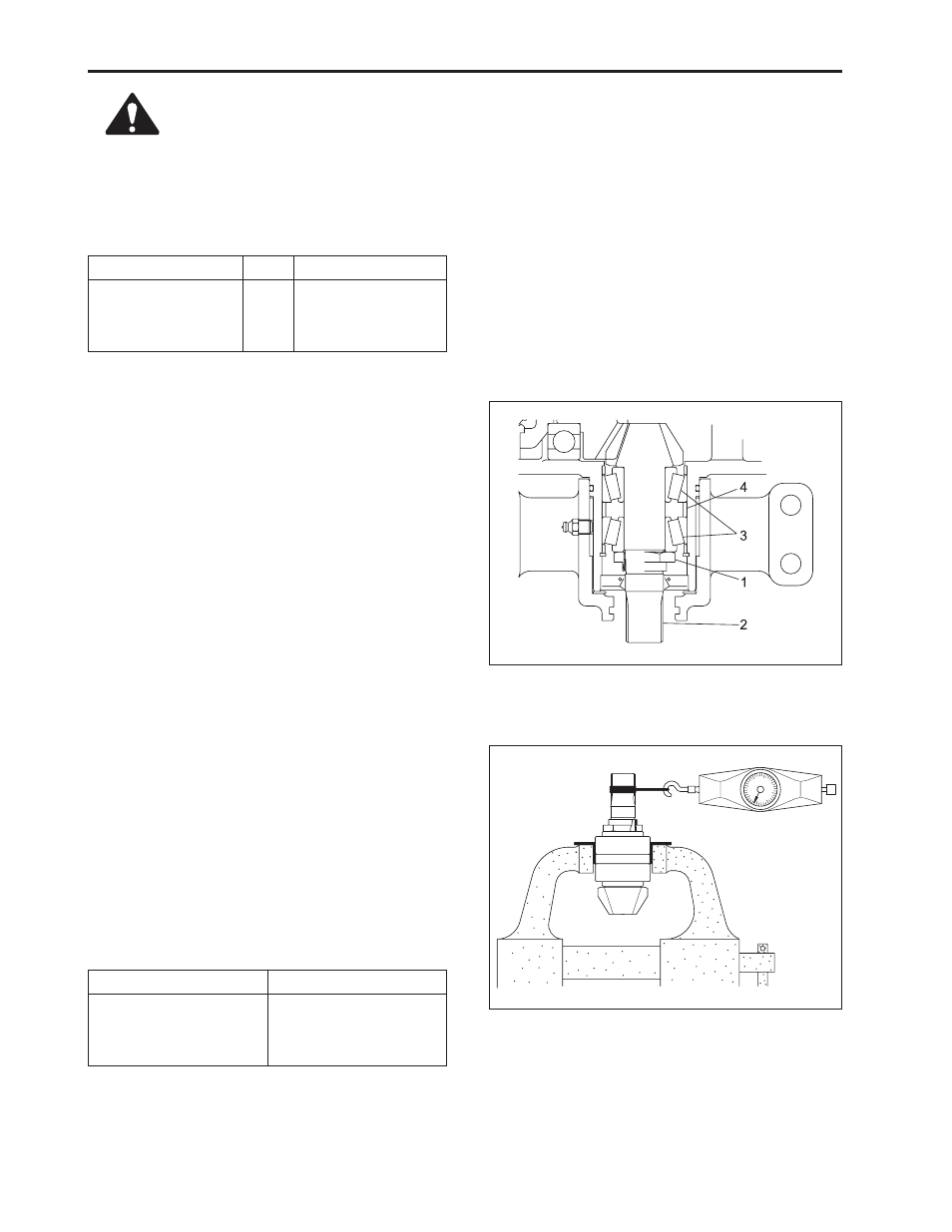
8.6 SIXTH STAGE (DISASSEMBLY OF
BEVEL PINION SHAFT)
1. Straighten cocking and loosen lock nut (1).
2. Remove taper roller bearing (3) from bevel pinion
shaft (2).
(When reassembling)
•
Make sure taper roller bearing assembly direction
is correct.
IMPORTANT:
•
When tightening lock nut, always check for bearing
backpressure.
(1) Lock Nut
(3) Taper Roller Bearing
(2) Bevel Pinion Shaft
(4) Spacer Barrel
A. How to Check Bearing Backpressure
•
Insert taper roller bearing and spacer barrel (4) into
pinion shaft and tighten lock nut by hand.
•
With bevel pinion shaft into assembly, lock the outer
of bearing into vice.
•
Wrap pinion shaft spline several times using rope,
pull out rope using push-pull gage and check for
rotation torque of pinion shaft.
•
If rotation torque exceeding the spec., loosen lock
nut and if less than the spec., tighten lock nut and
perform cocking so that the nut will not loosen.
Sect.
Specified value
Bevel pinion shaft
rotation torque
0.98 ~ 1.18 N·m
0.1 ~ 0.12 kgf·m
0.72 ~ 0.87 lbf·ft
•
When assembling DX bush (20), (21)
into front and rear brackets, align hole
of DX bush with assembly hole of
grease nipple (19) (See the following
figure).
•
Make sure the oil seal assembly di-
rection of bevel Pinion shaft is correct
(See the following figure).
CAUTION