Checking link configuration, Checking link configuration -12 – Rockwell Automation PLC-5 Fieldbus Solutions for Integrated Architecture User Manual User Manual
Page 98
Publication 1757-UM006A-EN-P - May 2002
4-12 Configurating the 1757-FIM
15. Click OK.
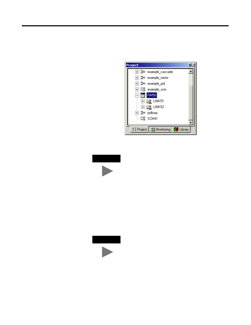
The FIM icon is added to the Project tab. The FIM also includes
icons for the two H1 fieldbus links that it supports.
Checking link configuration
Use the following steps to check the link configuration of the links
associated with a given FIM block. This procedure assumes that you
have configured a FIM block in the Project tab of Control Builder.
TIP
Refer to the 1757-FIM as a controller because the
module can function independently, without a
1757-PLX52.
TIP
You can configure a Link through the Project tab of
Control Builder without having the link installed.
However, some parameters on the Link configuration
form can only be viewed through the Monitoring tab
with the FIM and Link installed and communicating
with the system.
Be sure to click the plus sign in front of the FIM icon
to open its directory tree and expose the link icons.