Connecting the hardware, S - + s - + s - + s - + s – Rockwell Automation PLC-5 Fieldbus Solutions for Integrated Architecture User Manual User Manual
Page 253
Publication 1757-UM006A-EN-P May 2002
1788-CN2FF Installation Example F-5
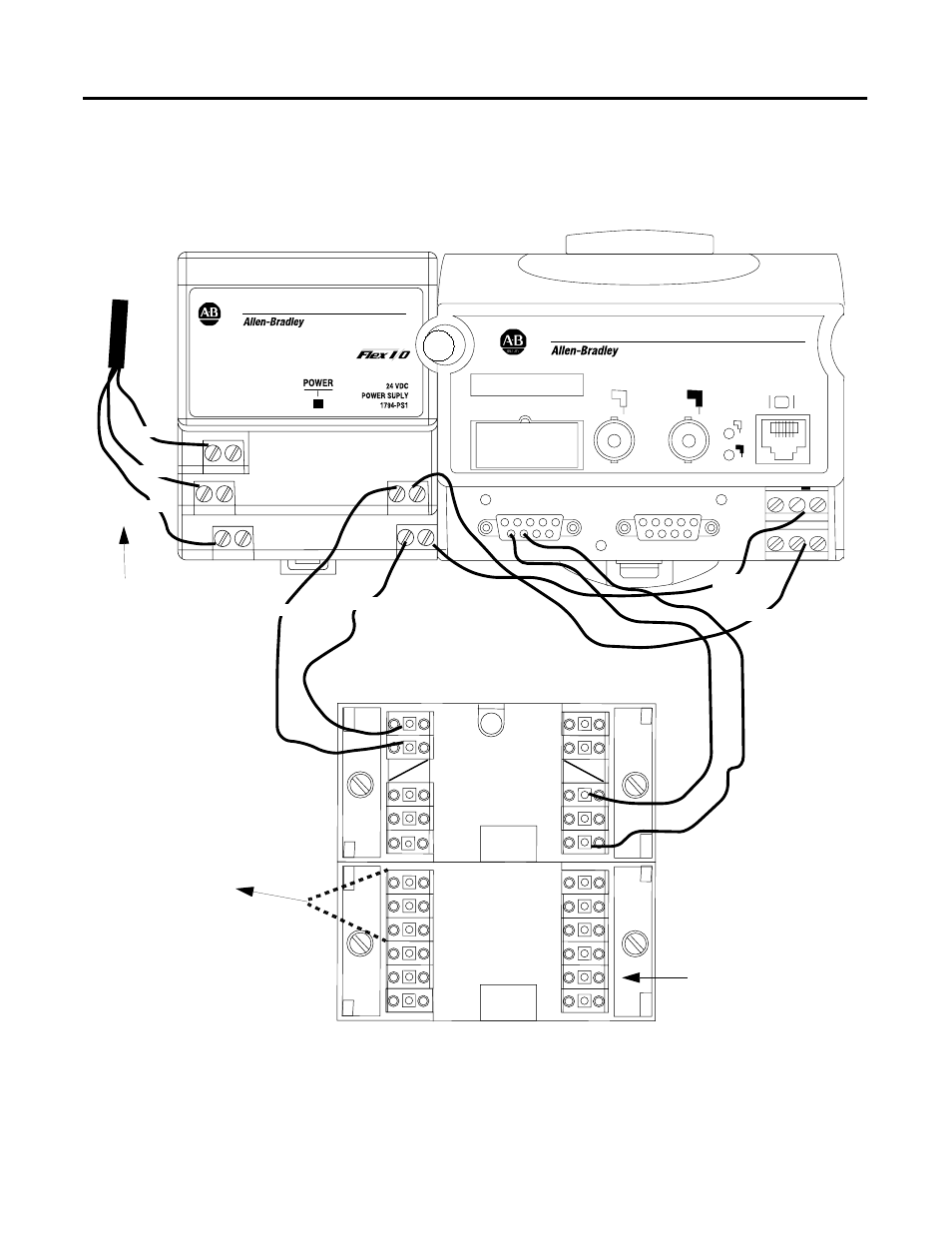
Connecting the Hardware
1. Wire the 1784-PS1, the 1788-CN2FF, and the Terminal Block as
shown in Figure F.2.
Figure F.2 Wiring the 1788-CN2FF
2. Connect the CN2FF and the other Fieldbus Devices to the
Relcom terminal block.
A
B
A
B
LINKING DEVICE
1788-CN2FF
F
OUNDATION™
F
IELDBUS
PORT 1
PORT 2
STATUS
1
2
+
-
+
s
-
V V V
C
+
-
+
s
-
+
s
-
+
s
-
+
s
-
+
s
-
Green
White
Black
White
Black
White
Black
AC Power
Connection
24 V Power
Connection
If indicator lights do not light, reverse
polarity of 24 V leads.
To open the connector, push down hard
on the small white lever.
Auxiliary Terminal Block
1788-CN2FF
1794-PS1
Fieldbus Power
Conditioner with
Terminators -
RELCOM INC
terminators used in
this example.
Wire to Fieldbus
device
ControlNet
Auxiliary Terminal Block
43187