Mai blocks, Mao blocks – Rockwell Automation PLC-5 Fieldbus Solutions for Integrated Architecture User Manual User Manual
Page 175
Publication 1757-UM006A-EN-P - May 2002
Using the 1788-CN2FF, ControlNet-to-FOUNDATION Fieldbus H1 Linking Device 7-15
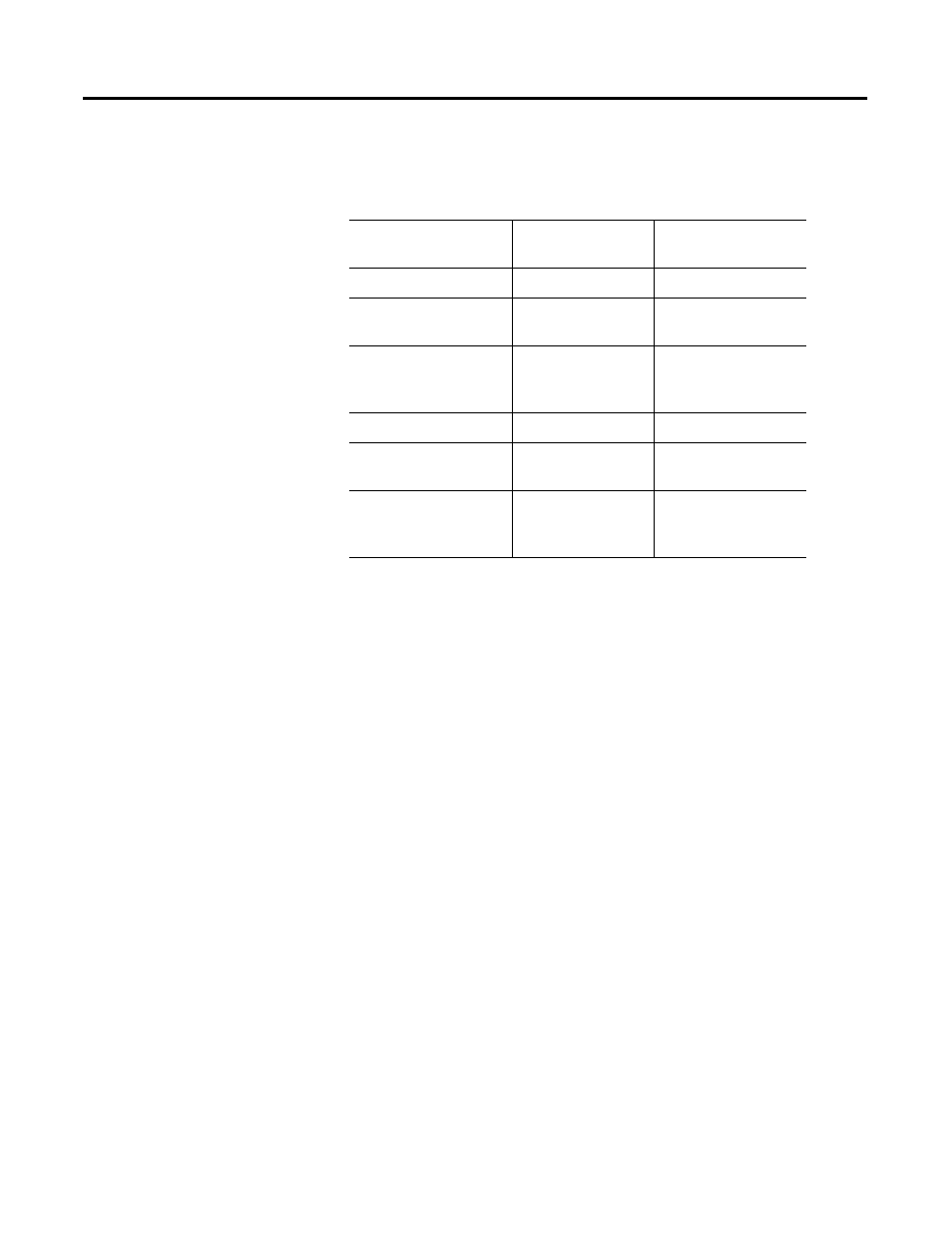
Table 7.E describes the attributes placed into the input and output
assembly for each object type.
MAI Blocks
For each MAI block configured in the linking device beginning with
the lowest numbered module, each channel that is connected to a
Fieldbus function block has attributes 3, 4, and 150 placed into the
required input assembly object. Each MAI channel requires 6 bytes in
the input assembly object.
MAO Blocks
For each MAO block configured in the linking device beginning with
the lowest numbered module, each channel that is connected to a
Fieldbus function block has attributes 3, 4, and 155 placed into the
required output assembly object. Additionally, if your controller
participates in cascade initialization for a specific channel (wiring
BKCAL_OUT from AO), attribute 154 is placed into the required input
assembly. Each MAO channel requires 6 bytes in the output assembly
object and 6 bytes in the input assembly, if cascade initialization is
performed—4 bytes in the input assembly if cascade initialization is
not performed.
Table 7.E Attributes in Input and Output Assemblies
Object Type
Attributes in Input
Assembly
Attributes in Output
Assembly
AI
3, 4, 150
AO
(CAScade initialization)
153, 154
3, 4, 155
AO
(NO CAScade
initialization)
153
3, 4, 155
DI
3, 4, 150
DO
(CAScade initialization)
153, 154
3, 4, 155
DO
(NO CAScade
initialization)
153
3, 4, 155