Interpreting component led indications, Fim led indications – Rockwell Automation PLC-5 Fieldbus Solutions for Integrated Architecture User Manual User Manual
Page 159
Publication 1757-UM006A-EN-P - May 2002
1757-FIM General Maintenance, Checkout, and Calibration 6-5
9. To automatically match the template, click in the Tag field to
expose the Match button. Click it to initiate enhanced matching
functions.
10. If a template exists, use The procedures in Chapter 4 to include
the device in the Control Strategy.
If a template does not exist, get the DD file for the device and
use the Fieldbus Library Manager to create one. Refer to Making
a Fieldbus Device Template from a Vendor's DD on page 4-17.
11. Include the fieldbus device in the control strategy and the Link
Active Schedule.
This completes the firmware upgrade.
12. Click OK.
The LINK Parameters window closes.
Interpreting Component
LED Indications
FIM LED indications
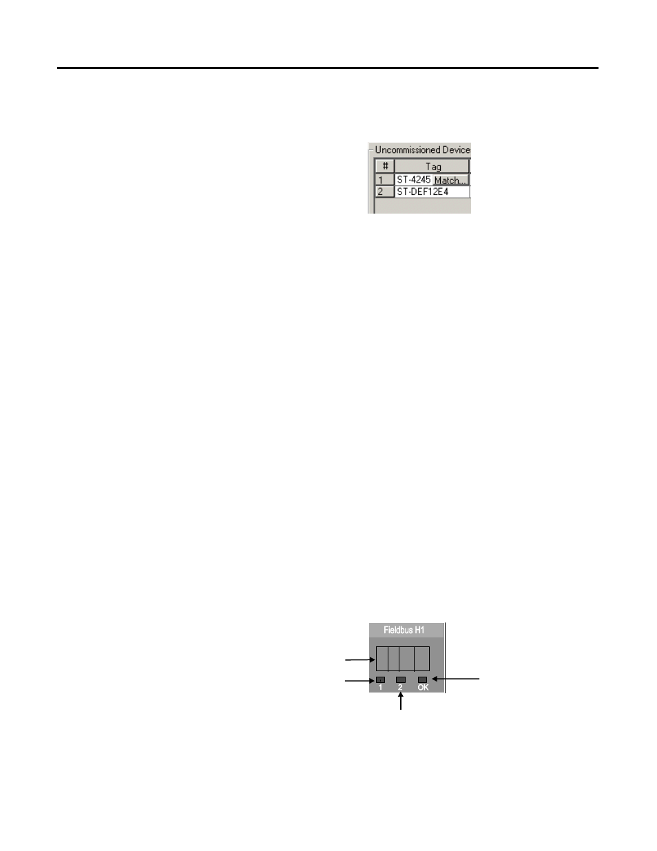
As shown in Figure 6.1, the FIM has one four-character display and
three two-color LEDs on its front panel. From left to right, the LEDs
provide Link 1 status, Link 2 status, and module health status,
respectively. The following table summarizes some typical indications
for reference.
Figure 6.1 FIM front panel indicators. Table 1 FIM LED Interpretations
4-Character
Display
Link 1 Status LED
1 - 1
0
Link 2 Status LED
Module Health LED