D - fieldbus wiring considerations, Fieldbus topologies, Fieldbus wiring considerations – Rockwell Automation PLC-5 Fieldbus Solutions for Integrated Architecture User Manual User Manual
Page 237: Appendix
1
Publication 1757-UM006A-EN-P - May 2002
Appendix
D
Fieldbus Wiring Considerations
The following wiring information is for general purposes only. Refer
to each device’s cooresponding wiring and installation instructions.
Fieldbus Topologies
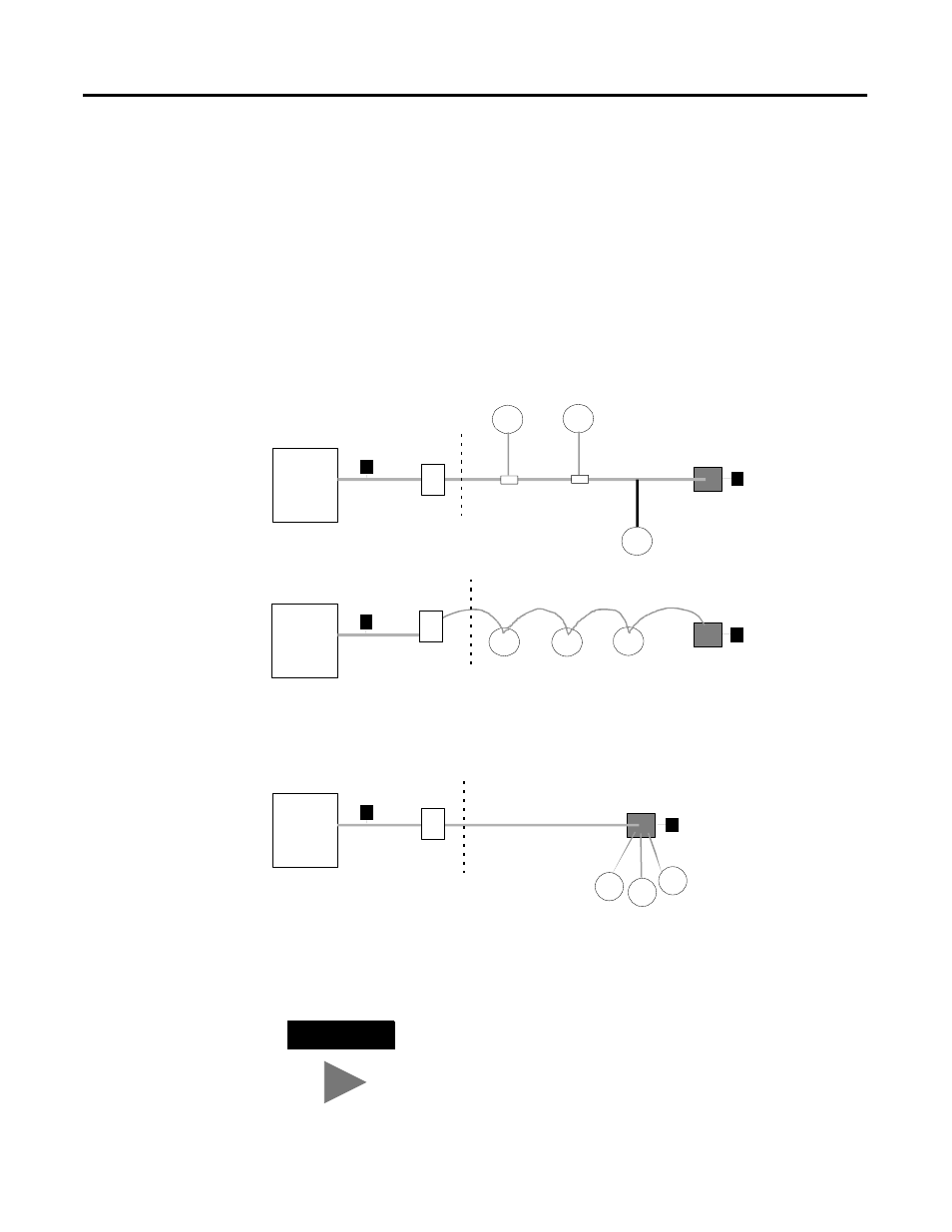
Figure D.1 illustrates the Spur, Daisy Chain, and Tree type wiring
topologies that can be used to connect fieldbus devices to one
another and a host.
Figure D.1 Overview of fieldbus wiring topologies
FD
FD
FD
FD
FD
FD
T
T
T
T
T
FD
FD
FD
T
Spur Topology
- Requires layout design
- Requires “T” connection
- Allows changing a device
without disturbing other devices
Daisy Chain Topology
- Requires layout design
- Requires terminators
- Difficult to replace one device
without stopping entire Fieldbus
- Difficult to maintain
Branch Topology
- Requires design evaluation
- Requires terminators
- Wiring savings are realized only
in “home run “cable
- Conforms to present practices
HOST
HOST
HOST
Terminator
Terminator
Terminator
Terminator
Terminator
Terminator
Junction Box
Junction Box
Junction Box
Spurs
(Unterminated)
“Home Run” Cable (Trunk)
“Home Run” Cable (Trunk)
I.S.
Barrier
(Optional)
I.S.
Barrier
(Optional)
I.S.
Barrier
(Optional)
PS
PS
PS
TIP
Maximum or acceptable cable distances may be
significantly reduced by using Non-FF spec wire.