Fieldbus device discrete output data integration – Rockwell Automation PLC-5 Fieldbus Solutions for Integrated Architecture User Manual User Manual
Page 59
Publication 1757-UM006A-EN-P - May 2002
Integrating Fieldbus into Rockwell Automation Logix System 2-15
Fieldbus device Discrete Output data integration
A user can functionally “wire” the output from a discrete process or
control value producing ProcessLogix function block like Device
Control to the input of a Discrete Output block in a fieldbus device
residing on an H1 link. The Fieldbus Library Manager (FLM) included
in the R400 Control Builder makes this possible. The FLM reads the
manufacturer's DD for the fieldbus device and creates a device
template that is included in the Project tab of Control Builder. The
device template includes the device's fieldbus function blocks, so it
can be configured and integrated with control strategies through
Control Builder.
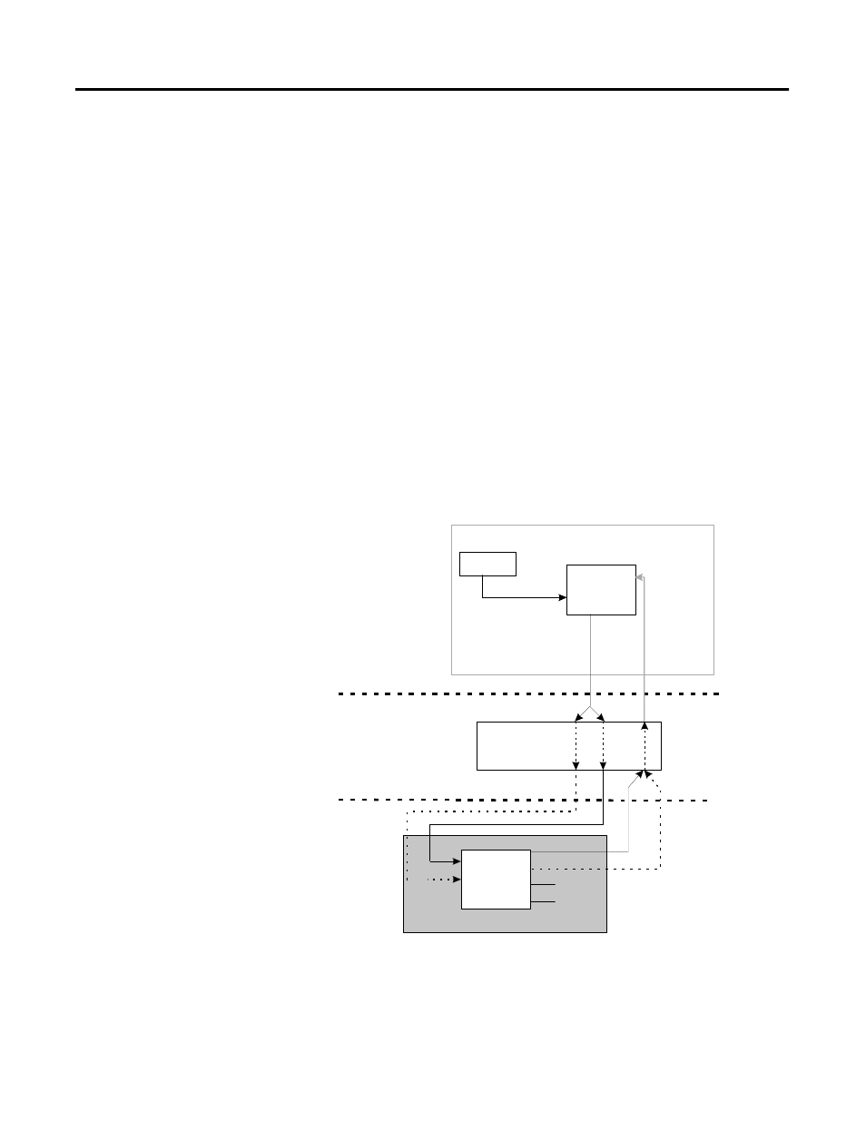
Figure 2.7 shows a simplified functional diagram of how the output
from a Device Control (DEVCTL) function block in a Control Module
that is assigned and loaded to the CEE in the Control Processor
Module (CPM) is integrated with a Discrete Output function block in a
fieldbus compliant device.
Figure 2.7 Integration of fieldbus device digital output signal with ProcessLogix
control strategy
CM
CPM/CEE
FIM
Fieldbus
Device
FIM
Digital
Output
Transducer
Device
Control
OUT_D
DI[1]
DO[1]
BACKCALIN = Back Calculation Input
BKCAL_OUT_D = Back Calculation Output Discrete
CAS_IN_D = Cascade Input Discrete
CEE = Control Execution Environment
CM = Control Module
CPM = Control Processor Module
DIC
CAS_IN
CAS_IN_D
RCAS_IN
RCAS_IN_D
RCAS_OUT_D
BKCAL_OUT_D
PVFL
BACKCALIN
DIC = Digital Input Channel
FIM = Fieldbus Interface Module
OP = Output
PVFL = Process Variable Flag
RCAS_IN_D = Remote Cascade Input Discrete
RCAS_OUT_D = Remote Cascade Output Discrete