Discrete input block, Discrete input block -17 – Rockwell Automation PLC-5 Fieldbus Solutions for Integrated Architecture User Manual User Manual
Page 31
Publication 1757-UM006A-EN-P - May 2002
The Fieldbus Communication Model 1-17
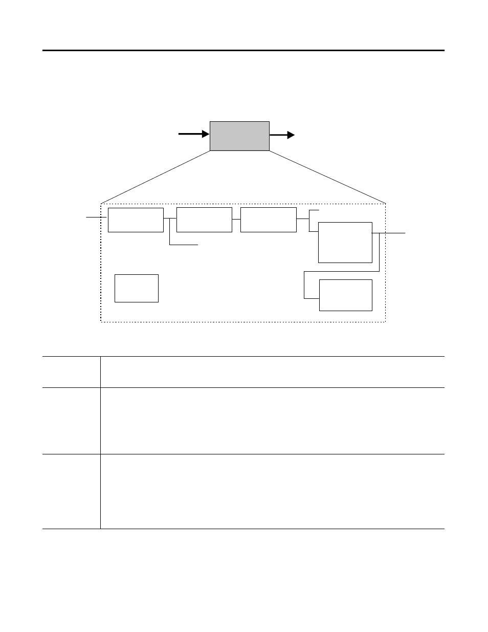
Discrete Input Block
Figure 1.8 Functional Schematic for Discrete Input Function Block
Table 1.H Discrete Input Block Specifications
Description
The Discrete Input function block takes the discrete input data from a selected Transducer block channel and provides
it as an output for other fieldbus function blocks. A functional schematic of the block is shown in Figure 1.8 for
reference.
Function Notes
• Supports Out of Service (OOS), Manual (Man), and Automatic (Auto) modes.
• The FIELD_VAL_D represents the true ON/OFF state of the value from the Transducer, using XD_STATE.
• Use the IO_OPTS Invert selection to do a Boolean NOT function between the field value and the output.
• Use the PV_FTIME to set the time that the input must be in one state before it gets passed to the PV_D.
• The PV_D is always the value that the block places in OUT_D, when the mode is Automatic.
• In Manual mode, if allowed, an operator can write a value to OUT_D.
• The SIMULATE_D parameter is for testing purposes only and always initializes in the disabled state.
Parameters
(see Appendix A
for definitions of
each parameter)
ACK_OPTION
ALARM_SUM
ALERT_KEY
BLOCK_ALM
BLOCK_ERR
CHANNEL
DISC_ALM
DISC_LIM
DISC_PRI
FIELD_VAL_D
GRANT_DENY
IO_OPTS
MODE_BLK
OUT_D
OUT_STATE
PV_D
PV_FTIME
SIMULATE_D
ST_REV
STATUS_OPTS
STRATEGY
TAG_DESC
UPDATE_EVT
XD_STATE
DI
Optional
Invert
Output
OUT_D
Mode
SHED_OPT
FIELD_VAL_D
Transducer
OUT
Simulate
SIMULATE_D
Alarms
DISC
Filter
PV_FTIME
CHANNEL
PV_D