Rockwell Automation PLC-5 Fieldbus Solutions for Integrated Architecture User Manual User Manual
Page 54
Publication 1757-UM006A-EN-P - May 2002
2-10 Integrating Fieldbus into Rockwell Automation Logix System
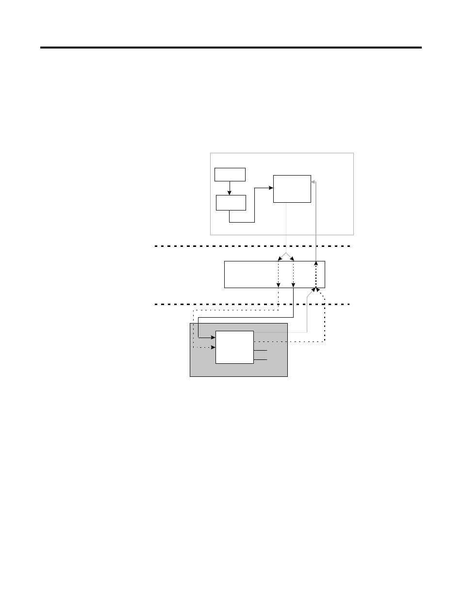
Figure 2.4 shows a simplified functional diagram of how the output
from a PID function block in a Control Module that is assigned and
loaded to the CEE in the Control Processor Module (CPM) is
integrated with an Analog Output function block in a fieldbus
compliant device.
Figure 2.4 Integration of a Fieldbus device analog output signal with ProcessLogix
control strategy
CM
CPM/CEE
FIM
Fieldbus
Device
FIM
Analog
Output
Transducer
PID
OUT
PV
OP
AIC = Analog Input Channel
BACKCALIN = Back Calculation Input
BKCAL_OUT = Back Calculation Output
CAS_IN = Cascade Input
CEE = Control Execution Environment
FIM = Fieldbus Interface Module
OP = Output
PID = Proportional, Integral, Derivative
CM = Control Module
CPM = Control Processor Module
DACQ = Data Acquistion
PV = Process Variable
RCAS_IN = Remote Cascade Input
RCAS_OUT = Remote Cascade Output
AIC
DACQ
CAS_IN
CAS_IN
RCAS_IN
RCAS_IN
RCAS_OUT
BKCAL_OUT
PV
P1
PV
BACKCALIN