Wiring blocks in cm101 for sample loop – Rockwell Automation PLC-5 Fieldbus Solutions for Integrated Architecture User Manual User Manual
Page 133
Publication 1757-UM006A-EN-P - May 2002
Configurating the 1757-FIM 4-47
Wiring blocks in CM101 for sample loop
1. In CM101 chart, double-click the OUT_VALUE pin on the
AI_LEVEL block.
The Pin is highlighted and cursor changes to cross-hairs
.
2. Move cursor over the P1 pin for the DATAACQ block and click.
A wire is drawn between the pins, the P1 pin is highlighted, and
the cursor reverts to its normal shape.
3. Repeat Steps 1 and 2 to wire the DATAACQ_101 PV pin to the
PID_101 PV and the PID_101 OP to the AO_FLOW
CAS_IN.VALUE. Be sure to add vertices where required by
clicking in the desired path to the final pin.
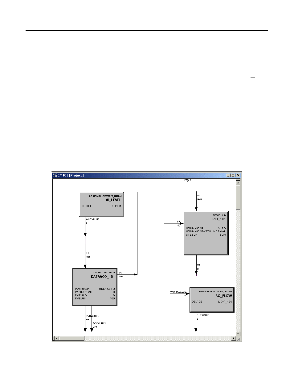
See Figure 4.3 for the completed CM101 with all blocks wired.
Figure 4.3 Completed CM101 for sample loop
This manual is related to the following products: