Fieldbus analog output or pid data manipulation – Rockwell Automation PLC-5 Fieldbus Solutions for Integrated Architecture User Manual User Manual
Page 55
Publication 1757-UM006A-EN-P - May 2002
Integrating Fieldbus into Rockwell Automation Logix System 2-11
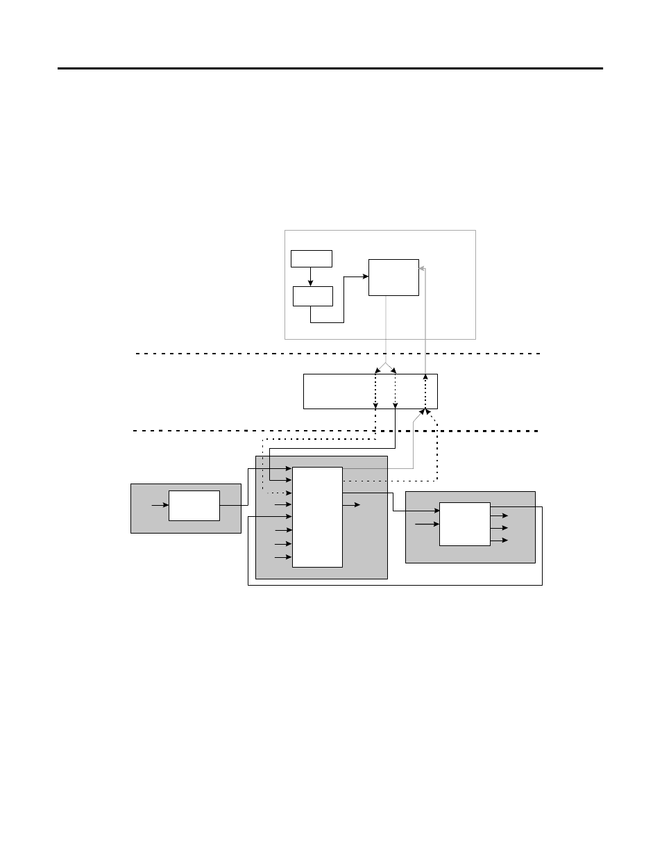
Figure 2.5 shows a simplified functional diagram of how the output
from a PID function block in a Control Module that is assigned and
loaded to the CEE in the Control Processor Module (CPM) is
integrated with a cascaded Proportional, Integral, Derivative function
block in a fieldbus compliant device.
Figure 2.5 Integration of fieldbus device PID control with ProcessLogix control
strategy
Fieldbus Analog Output or PID data manipulation
When the OP from the PID function block is wired to the CAS_IN
input for a fieldbus Analog Output or Proportional, Integral,
Derivative function block, the Control Builder automatically creates a
CEE output agent to handle the analog output to the fieldbus block.
CM
CPM/CEE
FIM
Fieldbus
Device
FIM
PID
PV
OP
AIC = Analog Input Channel
BACKCALIN = Back Calculation Input
BKCAL_IN = Back Calculation Input
BKCAL_OUT = Back Calculation Output
CAS_IN = Cascade Input
AIC
DACQ
CAS_IN
RCAS_IN
PID
ROUT_OUT
OUT
CAS_IN
RCAS_IN
RCAS_OUT
BKCAL_OUT
PV
P1
PV
BACKCALIN
Analog
Output
Transducer
OUT
CAS_IN
RCAS_IN
RCAS_OUT
BKCAL_OUT
IN
BKCAL_IN
ROUT_IN
TRK_IN_D
TRK_VAL
FF_VAL
Transducer
Analog
Input
OUT
CEE = Control Execution Environment
CM = Control Module
CPM = Control Processor Module
DACQ = Data Acquistion
FIM = Fieldbus Interface Module
OP = Output
PID = Proportional, Integral, Derivative
PV = Process Variable
RCAS_IN = Remote Cascade Input
RCAS_OUT = Remote Cascade Output
ROUT_OUT = Remote Out Output