Display indications and mode calculation, Display indications and mode calculation -23 – Rockwell Automation PLC-5 Fieldbus Solutions for Integrated Architecture User Manual User Manual
Page 67
Publication 1757-UM006A-EN-P - May 2002
Integrating Fieldbus into Rockwell Automation Logix System 2-23
Display indications and mode calculation
The fieldbus mode indications for actual mode and composite
actual/target modes will appear in the following formats on Station
displays as shown in Table 2.H.
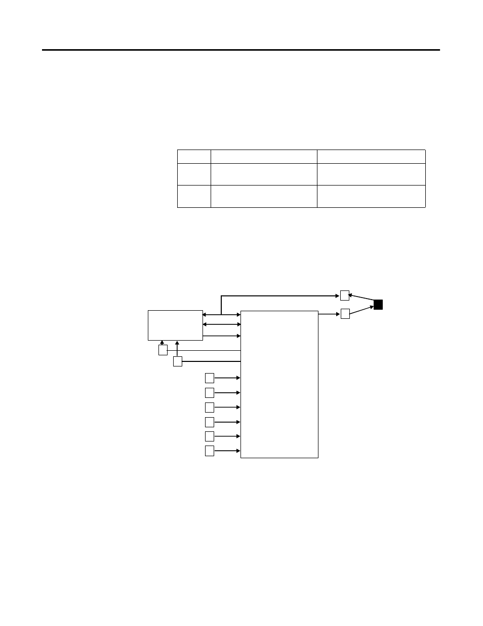
The block mode calculation of actual mode considers the input
parameter status attributes, input values, and resource state as
represented graphically in Figure 2.8.
Figure 2.8 Block mode calculation summary
See Appendix C for list of conditions, which will change the mode in
order of priority with Good (Non-Cascade) status on input parameter
as the lowest priority.
Table 2.H Fieldbus mode indications
Format
Description
Examples
a
Satisfied in mode a; actual same
as target.
OOS, MAN, AUTO, CAS, RCAS,
ROUT
a (t)
In mode a; not satisfied in higher
target mode t.
MAN (A), CAS (RC), IM (A), LO
(CAS), AUTO (M), CAS (M)
Determine
Host Timeout
Mode
Actual Mode
and Target
Remote Cascade
Remote Out
Shed Option
Cascade
Primary Input
Back Calculation Input
Resource State
Block Specific Inputs
Actual and Target
Mode Calculation
Target Mode