Dip switch and jumper settings, Do not use - for engineering use only – Rockwell Automation 23P PowerFlex Digital DC Drive User Manual
Page 75
Rockwell Automation Publication 20P-UM001K-EN-P - July 2014
75
Installation and Wiring
Chapter 1
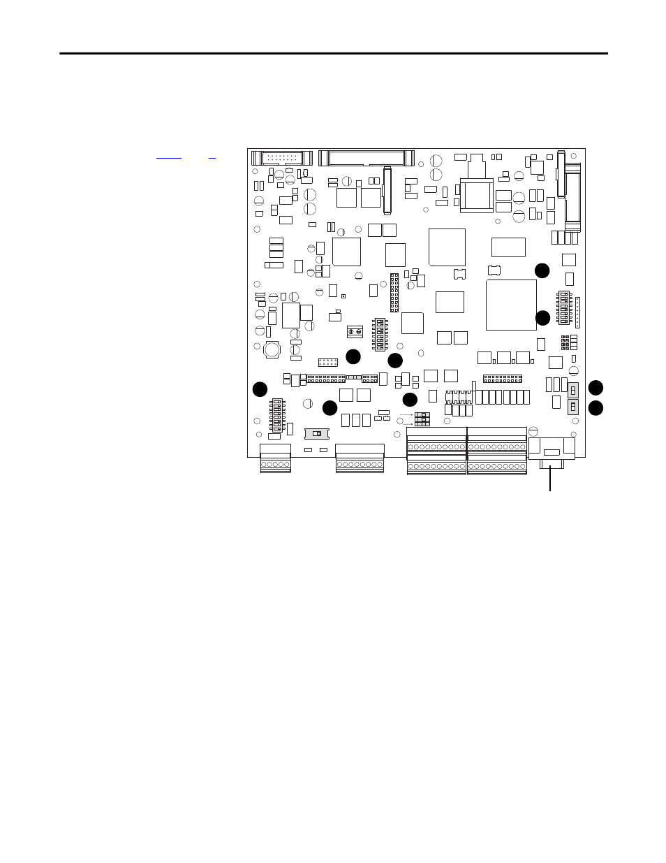
DIP Switch and Jumper
Settings
DIP switches and jumpers on the control circuit board are used to configure the
drive for flashing firmware to the control board EEPROM, the appropriate speed
feedback device settings, analog input signals and minimum field current.
Figure 55 - Control Circuit Board DIP Switch and Jumper Locations
- A B C +
A+ A- B+ B- Z+ Z- COM +V
A+ A- B+ B- Z+ Z- COM +V
- A B C +
21 22 23 24 25 26 27 28 29 30
1 2 3 4 5 6 7 8 9 10
31 32 33 34 35 36 37 38 39 40
11 12 13 14 15 16 17 18 19 20
21 22 23 24 25 26 27 28 29 30
1 2 3 4 5 6 7 8 9 10
11 12 13 14 15 16 17 18 19 20
31 32 33 34 35 36 37 38 39 40
DEBUG
S15
S3
S2
S1
S0
RST
ACT
RUN
PWR
1 2 3 4 5 6 7 8
S18
S12
S10
S21
ENC_5 ENC_12
S4
1 2 3 4 5 6 7 8
S14
1 2 3 4 5 6 7 8
S20
S11
S9
ON
ON
See
on page
for
descriptions corresponding to
the ID numbers shown here.
1
6
9
2
3
8
5
4
7
Do not use - for
engineering use only.