Rockwell Automation 23P PowerFlex Digital DC Drive User Manual
Page 290
290
Rockwell Automation Publication 20P-UM001K-EN-P - July 2014
Appendix C
Application Notes
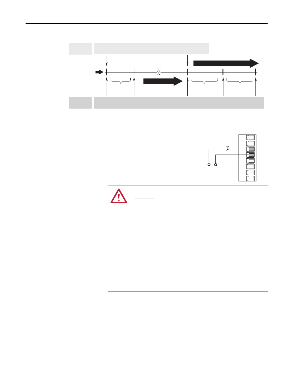
Figure 86 - Torque Proving Flow Diagram
(1) For torque proving to function properly, a mechanical brake must be
wired to a relay output.
Torque
Prove Initiated
Brake
Released
Float
Initiated
Brake
(1)
Set
Brake
Slip Test
Run
Command
Run
Command Released
Drive Running
Run can be initiated anytime
All times between Drive Actions are programmable and can be made very small
(i.e. Brake Release Time can be 0.1 seconds)
[ZeroSpdFloatTime]
Parameter 1113
[Brk Release Time]
Parameter 1107
[Brk Set Time]
Parameter 1108
Operator
Commands
Time
Drive
Actions
ATTENTION: User must read the following prior to the use of TorqProve without
an encoder.
Encoderless TorqProve must be limited to lifting applications where personal safety
is not a concern. Encoders offer additional protection and must be used where
personal safety is a concern. Encoderless TorqProve cannot hold a load at zero
speed without a mechanical brake and does not offer additional protection if the
brake slips/fails. Loss of control in suspended load applications can cause personal
injury and/or equipment damage.
It is the responsibility of the engineer and/or user to configure drive parameters,
test any lifting functionality and meet safety requirements in accordance with all
applicable codes and standards. If encoderless TorqProve is desired, the user must
certify the safety of the application. To acknowledge that the end user has read this
“Attention” and properly certified their encoderless application, parameter 414
[Fdbk Device Type] must be changed to “DC Tach” (2). This will allow bit 1 of
parameter 1100 [Torq Prove Cfg] to be changed to a “1” without causing a Type 2
alarm when lifting/torque proving is enabled (Par 1100, bit 0 = 1).
Control
Voltage
78
79
35
36
75
76
U2
V2
Brake
Relay