Rockwell Automation 23P PowerFlex Digital DC Drive User Manual
Page 182
182
Rockwell Automation Publication 20P-UM001K-EN-P - July 2014
Chapter 3
Programming and Parameters
U
TIL
IT
Y
Al
arms
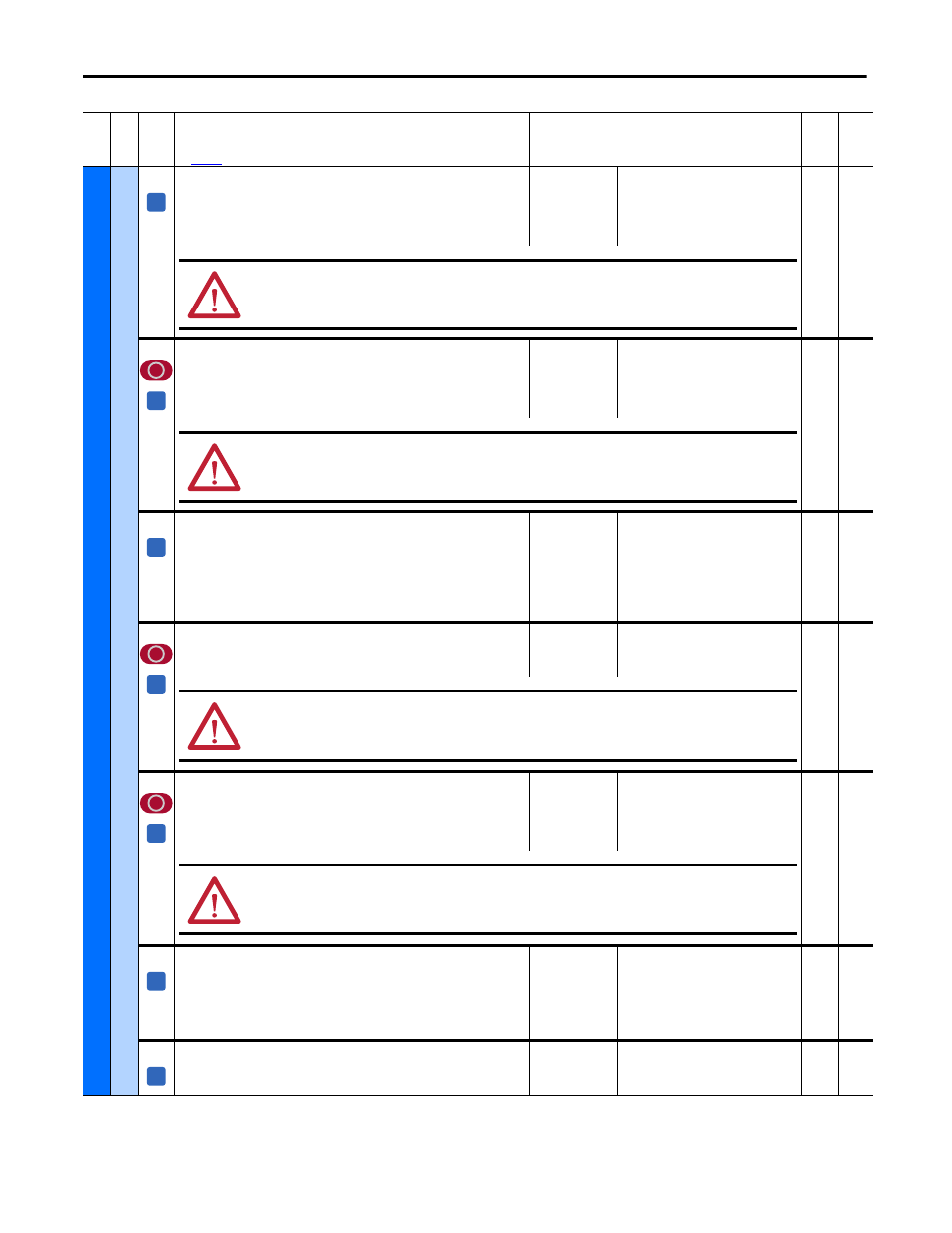
470
[UnderVlt Flt Dly]
Configures the length of time that an AC Line undervoltage condition can persist
before an AC undervoltage fault (F4) is activated. The condition must persist for
the entire delay time or the delay timer is reset.
Note: This parameter was added for firmware version 6.001.
Default:
Min/Max:
Units:
10
0 / 100
ms
16-bit
Int
473
[FldLoss Flt Cfg]
Determines the response of the drive to a field loss condition (F6 “Fld Current
Loss”). If Par 497 [Field Reg Enable] is set to 0 “Disabled”, set this parameter to
0 “Ignore”.
Note: See Chapter 4 for a list of alarm and fault descriptions.
Default:
Options:
2 =
0 =
1 =
2 =
“Fault”
“Ignore”
“Alarm”
“Fault”
16-bit
Int
497
475
[FldLoss Flt Dly]
Configures the length of time that the measured field current feedback can be less
than one half of Par 468 [Min Fld Curr Pct] before a field loss condition (fault or
alarm) is activated. The condition must persist for the entire delay time or the
delay timer is reset. Note that this parameter is not used when armature voltage
speed feedback is configured. Note: This parameter was added for firmware
version 6.001.
Default:
Min/Max:
Units:
500
0 / 5000
ms
16-bit
Int
468
478
[Spd Loss Flt Cfg]
Determines the response of the drive to a speed feedback loss condition.
Note: See Chapter 4 for a list of fault and alarm descriptions.
Default:
Options:
2 =
1 =
2 =
“Fault”
“Alarm”
“Fault”
16-bit
Int
458
479
[MtrOvrld Flt Cfg]
Determines the response of the drive to a motor overload condition (F7 “Motor
Overload”).
Notes: See Chapter 4 for a list of fault and alarm descriptions. This parameter was
added for firmware version 3.001.
Default:
Options:
2 =
0 =
1 =
2 =
“Fault”
“Ignore”
“Alarm”
“Fault”
16-bit
Int
376,
1290
481
[UnderVolt Thresh]
The AC input voltage level below which an undervoltage fault (F4 “AC
Undervoltage”) will be detected. A typical value is 85% of the nominal AC line
voltage (Par 466 [AC Line Voltage]). This fault can only occur while the drive is
running.
Note: See Chapter 4 for a list of fault descriptions.
Default:
Min/Max:
Units:
230
0 / 1000
Vac
16-bit
Int
584
[OverCurrent Thr]
Value at which an overcurrent condition (F13 “Overcurrent”) will be detected.
Note: See Chapter 4 for a list of fault descriptions.
Default:
Min/Max:
Units:
175
0 / 250
%
16-bit
Int
Fil
e
Gr
oup
No
.
Parameter Name & Description
See
page 114
for symbol descriptions
Values
Da
ta
T
yp
e
Rela
ted
A
ATTENTION: Setting this value incorrectly for the application could result in damage to the drive SCR(s) and or fuses.
A
ATTENTION: Setting this parameter to 0 “Ignore” or 1 “Alarm”, could result in motor and/or equipment damage. If set to
“Ignore” or “Alarm”, it is strongly recommended that an external means of protecting against this condition be provided.
A
A
ATTENTION: Par 478 [Spd Loss Flt Cfg] must be set to 1 “Fault” if Par 458 [SpdReg FB Bypass] is set to 0 “Disabled”. Failure
to observe this precaution could result in high motor speeds, equipment damage, and/or bodily injury if a “Spd Fdbk Loss”
alarm condition were encountered.
A
ATTENTION: Setting Par 479 [MtrOvrld Flt Cfg] to 0 “Ignore” or 1 “Alarm”, could result in motor and/or equipment damage.
Verify that the motor is properly sized for the application and that a separate device is installed that monitors for and
signals a motor overload condition.
A
A