Rockwell Automation 23P PowerFlex Digital DC Drive User Manual
Page 131
Rockwell Automation Publication 20P-UM001K-EN-P - July 2014
131
Programming and Parameters
Chapter 3
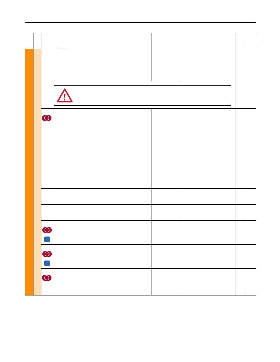
MO
TO
R C
O
NTROL
Fi
el
d Co
n
fi
g
468
[Min Fld Curr Pct]
Minimum allowable field current. The value set in this parameter also
influences the threshold at which the “Fld Current Loss” (F6) fault occurs. The
threshold is half of the value of Par 468 [Min Fld Curr Pct]. The value of Par
351 [Field Current] equals the value of this parameter when Par 499 [Field
Economy En] = 1 “Enabled” and Field Economy becomes active. Leave set to
the default value for permanent magnet motor applications.
Default:
Min/Max:
Units:
30
0 / Par 467 [Max Fld Flux Pct]
%
16-bit
Int
467,
499
469
[Field Mode Sel]
Operating mode of the field controller.
• “Base Speed” = The motor field is regulated with constant current and
controls the motor from zero to base speed. If a curve is defined through
Pars 916, 917 and 918 [Fld Const xx Pct], this value will change linearly
through Par 467 [Max Fld Flux Pct] (which is a percentage of the nominal
flux value set in Par 280 [Nom Mtr Fld Amps]).
• “Field Weaken” = The motor field is regulated with a combination of
torque and constant power (armature and field regulation -- field
weakening). The maximum armature voltage is configured in Par 175
[Rated Motor Volt]. When using a DC contactor, this parameter is set to
this option, and Par 458 [SpdReg FB Bypass] is set to 1 “Enabled,” the
armature voltage feedback terminals A1 and A2 must be connected to the
motor terminals A1 and A2, respectively.
• “External” = The motor field power is supplied by an external rectifier/
converter (the drive’s field output is disabled).
• “PM External” = External field created by a permanent magnet (PM)
motor.
Note: Option 3 “PM External” was added for firmware version 5.002.
Default:
Options:
0 =
0 =
1 =
2 =
3 =
“Base Speed”
“Base Speed”
“Field Weaken”
“External”
“PM External”
16-bit
Int
456,
916,
917,
918,
921
493
[Arm Volt Kp]
Proportional gain (K
P
) of the field voltage regulator expressed as a
percentage of the value defined in Par 495 [Arm Volt Kp Base].
Default:
Min/Max:
Units:
30.00
0.00 / 100.00
%
Real
495
494
[Arm Volt Ki]
Integral gain (K
I
) of the field voltage regulator expressed as a percentage of
the value defined in Par 496 [Arm Volt Ki Base].
Default:
Min/Max:
Units:
40.00
0.00 / 100.00
%
Real
496
495
[Arm Volt Kp Base]
The proportional gain (K
P0
) of the field voltage regulator (base value).
Default:
Min/Max:
Units:
Based on drive current rating
0.10 / Based on drive current rating
A / V
Real
493
496
[Arm Volt Ki Base]
The integral coefficient (K
I0
) of the field voltage regulator (base value).
Default:
Min/Max:
Units:
0.90 x P496
max
0.01 / Based on drive current rating
A / V / ms
Real
494
497
[Field Reg Enable]
Enables/Disables the field regulator. Leave set to the default value for
permanent magnet motor applications.
• “Enabled” = The field regulator is enabled and controlling the field
output.
• “Disabled” = The field regulator is disabled (the field current is zero).
Default:
Options:
1 =
0 =
1 =
“Enabled”
“Disabled”
“Enabled”
16-bit
Int
Fil
e
Gr
oup
No
.
Parameter Name & Description
See
page 114
for symbol descriptions
Values
Da
ta
T
yp
e
Rela
ted
ATTENTION: Failure to set this parameter to a value appropriate for the intended application could result in excessive
motor speed, equipment damage, and/or personal injury.
A
A