Rockwell Automation 23P PowerFlex Digital DC Drive User Manual
Page 177
Rockwell Automation Publication 20P-UM001K-EN-P - July 2014
177
Programming and Parameters
Chapter 3
U
TIL
IT
Y
Di
ag
n
os
ti
cs
397
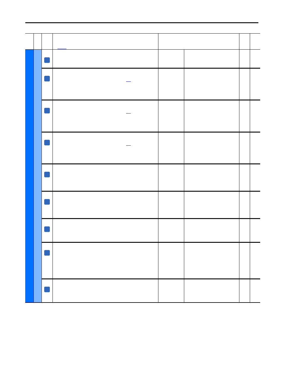
[MOP Dec Active]
Indicates whether the drive is decelerating using the preselected ramp.
• 0 “No Decel” = The drive is not decelerating using a preselected ramp
• 1 “Decel” = The drive is decelerating using a preselected ramp
Default:
Min/Max:
Read Only
0 / 1
16-bit
Int
400
[Spd Select 0]
Indicates the state of the assigned digital input, [Digital Inx Sel], set to 17 “Speed
Sel 1”. See Option Definitions for [Digital Inx Sel] on page
for instructions on
how to set digital input speed selects to different speed references.
• “0” = Digital input [Digital Inx Sel] set to 17 “Speed Sel 1” not asserted
• “1” = Digital input [Digital Inx Sel] set to 17 “Speed Sel 1” asserted
Note: By default, the state of this parameter is determined by digital input 5.
Default:
Min/Max:
Read Only
0 / 1
16-bit
Int
401,
402
401
[Spd Select 1]
Indicates the state of the assigned digital input, [Digital Inx Sel], set to 18 “Speed
Sel 2”. See Option Definitions for [Digital Inx Sel] on page
for instructions on
how to set digital input speed selects to different speed references.
• “0” = Digital input [Digital Inx Sel] set to 18 “Speed Sel 2” not asserted
• “1” = Digital input [Digital Inx Sel] set to 18 “Speed Sel 2” asserted
Note: By default, the state of this parameter is determined by digital input 6.
Default:
Min/Max:
Read Only
0 / 1
16-bit
Int
400,
402
402
[Spd Select 2]
Indicates the state of the assigned digital input, [Digital Inx Sel], set to 19 “Speed
Sel 3”. See Option Definitions for [Digital Inx Sel] on page
for instructions on
how to set digital input speed selects to different speed references.
• “0” = Digital input [Digital Inx Sel] set to 19 “Speed Sel 3” not asserted
• “1” = Digital input [Digital Inx Sel] set to 19 “Speed Sel 3” asserted
Note: By default, the state of this parameter is determined by digital input 7.
Default:
Min/Max:
Read Only
0 / 1
16-bit
Int
400,
401
403
[Ramp Select 0]
Indicates the state of the assigned digital input, [Digital Inx Sel], set to 25 “Acc2 &
Dec2” or 26 “Accel 2”.
• “0” = Accel 1 ramp rate is selected
• “1” = Accel 2 ramp rate is selected
Note: This parameter can be assigned to indicate the state of a digital input.
Default:
Min/Max:
Read Only
0 / 1
16-bit
Int
404
404
[Ramp Select 1]
Indicates the state of the assigned digital input, [Digital Inx Sel], set to 25 “Acc2 &
Dec2” or 27 “Decel 2”.
• “0” = Decel 1 ramp rate is selected
• “1” = Decel 2 ramp rate is selected
Note: This parameter can be assigned to indicate the state of a digital input.
Default:
Min/Max:
Read Only
0 / 1
16-bit
Int
403
432
[Reslvr Error Cnt]
Increments (16-bit unsigned) for every SSI communication message that contains
an error (for example, CRC). The value of this parameter is reset to zero at drive
power-up or when the “Clear Faults” function is used.
Note: This parameter was added for firmware version 5.002.
Default:
Min/Max:
0
0 / 65536
Read
Only
651
[Spd Fdbk State]
Indicates the status of the selected speed feedback device (DC tach, encoder, or
resolver). A speed feedback loss can be configured as a fault or alarm in Par 478
[Spd Loss Flt Cfg].
• “0” = Error
• “1” = OK
Notes: This parameter can be assigned to a digital output. The name of this
parameter was changed from [Encoder State] for firmware version 5.002.
Default:
Min/Max:
Read Only
0 / 1
16-bit
Int
414,
478
1290 [MtrOvrld Status]
Current percentage of motor overload (100% = motor overload). The current
percentage displays regardless of the configuration of the motor overload
condition (Par 479 [MtrOvrld Flt Cfg] = Fault, Alarm, or Ignore).
Note: This parameter was added for firmware version 3.001.
Default:
Min/Max:
Units:
Read Only
0 / 100
%
Real
376,
479
Fil
e
Gr
oup
No
.
Parameter Name & Description
See
page 114
for symbol descriptions
Values
Da
ta
T
yp
e
Rela
ted
A
A
A
A
A
A
A
A
A